EasyManuals Logo

DEWESOFT IOLITE V22-2 User Manual

Default Icon
193 pages
To Next Page IconTo Next Page
To Previous Page IconTo Previous Page
Page #170 background imageLoading...
Page #170 background image
IOLITE®
TECHNICAL REFERENCE MANUAL
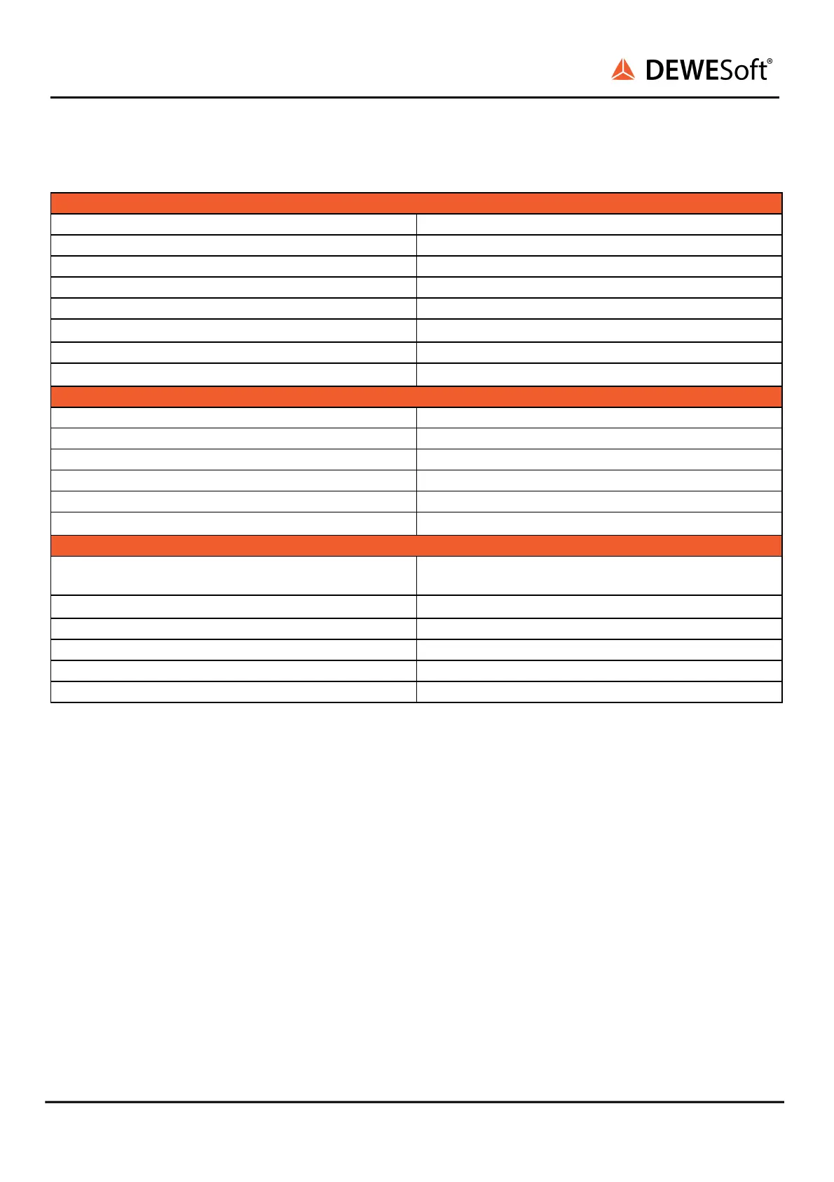
4.7.3.1. IOLITEr-8xDI-4xDO: Specifications
Digital Input
Isolated Input Channels
8
Input low level
-1 V ~ +1 V
Input high level
-48 V ~ -3 V, +3 V ~ +48 V
Input high current @ 5 V
UIN < 1 mA
Input high current @ 30 V
UIN < 1 mA
Sampling rate
Simultaneous 40 kS/s
Overvoltage protection
100 V continuous (250 Vpeak)
Isolation voltage peak
1000 V Isolated common GND
Digital Output
Isolated Output Channels
4
Compatibility
Solid state relay
Maximum sink current
0.5 A
Maximum switching voltage
50 V
Maximum update rate
depending on EtherCAT master
Isolation voltage peak
1000 V Isolated common GND
Additional Specifications
Input connectors
Terminal block (3 x 2 pole, 2 x 12 pole, 1 x 8 pole)
OMNIMATE SL 2.50 / BLF 2.50/180
Power supply
9 - 48 V DC
Power out
max. 2 A (unprotected)
Power consumption
Typ. 1.1 W, Max. 1.8 W
Weight
184 g
Slice Dimensions
128.4 x 115.4 x 30.1 mm
4.7.3.2. IOLITEr-8xDI-4xDO: Connectors
IOLITEr-8xDI-4xDO modules have 2-pin terminal block connector for external power supply and two
time 12-pin terminal block connectors for digital inputs.
Additionally there is 2-pin terminal block connector for external power supply and 8-pin terminal block
connector for digital outputs.
Digital IN and OUT banks are isolated from each other.
Additionally, there is a 2-pin terminal block connector for PWR OUT function.
All terminal block connectors have a 2.50 mm pitch.
IOLITE® V22-2 170 / 193

Table of Contents

Questions and Answers:

Question and Answer IconNeed help?

Do you have a question about the DEWESOFT IOLITE V22-2 and is the answer not in the manual?

DEWESOFT IOLITE V22-2 Specifications

General IconGeneral
BrandDEWESOFT
ModelIOLITE V22-2
CategoryNetwork Hardware
LanguageEnglish