EasyManuals Logo

DEWESOFT IOLITE V22-2 User Manual

Default Icon
193 pages
To Next Page IconTo Next Page
To Previous Page IconTo Previous Page
Page #91 background imageLoading...
Page #91 background image
IOLITE®
TECHNICAL REFERENCE MANUAL
4.1.3.2.1. IOLITEr-16xLV: T2A2f Power OUT Connector: Pinout
LV connector: pin-out (TBLOCK male)
Pin
Name
Description
1
+PWR OUT
V
supply
output
2
-PWR OUT
Non-isolated GND
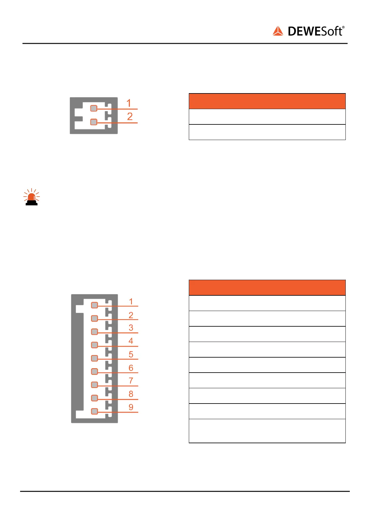
Connector (on the device): OMNIMATE Signal SL 2.50/02/90G
Mating connector (for the cable): OMNIMATE Signal BLF 2.50/02/180
Caution
PWR OUT pins are intended to supply external loads. Do not connect the external power supply
to the PWR OUT pins! It can damage the equipment.
Current limit of PWR OUT source is 2 A per module.
Current limit of the IOLITE system is 16 A!
4.1.3.2.2. IOLITEr-16xLV: T2A9f Analog input: Pinout
Analog in connector: pin-out (terminal block male)
Pin
Name
Description
1
IN 1 +
Analog input 1
2
IN 1 -
Input ground 1
3
IN 2 +
Analog input 2
4
IN 2 -
Input ground 2
5
IN 3 +
Analog input 3
6
IN 3 -
Input ground 3
7
IN 4 +
Analog input 4
8
IN 4 -
Input ground 4
9
iGND
Common isolated
ground
AI connector (on the device): OMNIMATE Signal SL 2.50/09/90G
Mating connector (for the cable): OMNIMATE Signal BLF 2.50/09/180
IOLITE® V22-2 91 / 193

Table of Contents

Questions and Answers:

Question and Answer IconNeed help?

Do you have a question about the DEWESOFT IOLITE V22-2 and is the answer not in the manual?

DEWESOFT IOLITE V22-2 Specifications

General IconGeneral
BrandDEWESOFT
ModelIOLITE V22-2
CategoryNetwork Hardware
LanguageEnglish