IOLITE®
TECHNICAL REFERENCE MANUAL
3.3.3.3. IOLITE-R8r: Ruggedized Boxed Chassis: Connectors
The IOLITE-R8r chassis also enables dual EtherCAT bus. There are two 8-pin LEMO 1T connectors on the
back panel of IOLITE-R8r used for data transfer and synchronisation on the primary bus (BUS 1) for
buffered data. The OUT connector on BUS 1 also enables power supply for external Dewesoft EtherCAT
devices.
Secondary bus (BUS 2) for unbuffered data has two RJ45 connectors (IN and OUT) for data transfer and
synchronization to 3rd party control master.
Two 2-pin LEMO 1T connectors are used for redundant power supply (PWR IN).
Above the PWR IN connector is a GND socket for grounding the IOLITE-R8r.
Synchronization with Dewesoft USB data acquisition devices or connection to clock master is on
IOLITE-R8r enabled by connecting a synchronization cable to two SYNC inputs (4-pin LEMO 00).
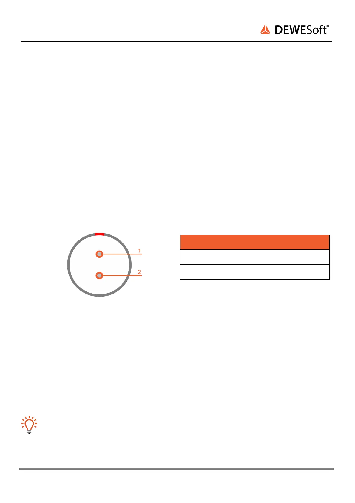
3.3.3.3.1. IOLITE-R8r: Ruggedized Boxed Chassis: Power in: Pinout
Power in connector: pin-out (2-pin LEMO male)
For the power supply an unregulated DC voltage
between 9 and 48 Volts is required, which is
connected to the LEMO 1B connector on the rear
side of the chassis.
PWR IN connector (on the device): ECJ.1B.302.CLA
Mating connector (for the cable): FGJ.1B.302.CLLD42Z
3.3.3.3.2. IOLITE-R8r: Ruggedized Boxed Chassis: Sync: Pinout
The sync connectors are required when you want to synchronize the data from IOLITE with Dewesoft
USB devices for the same measurement. The signal that is transferred over sync cable makes sure that
the measurement data of IOLITE and Dewesoft USB devices are perfectly synchronized to each other.
The other use of a sync connector is to connect directly to IOLITE a signal from the clock master.
Hint
There is no distinction between the IN and OUT – it does not matter which connector you use.
When IRIG-synchronisation is used, the IRIG signal is on pins 1, 2.