EasyManuals Logo

DEWESOFT IOLITE V22-2 User Manual

Default Icon
193 pages
To Next Page IconTo Next Page
To Previous Page IconTo Previous Page
Page #174 background imageLoading...
Page #174 background image
IOLITE®
TECHNICAL REFERENCE MANUAL
4.7.3.2.5. IOLITEr-8xDI-4xDO: Digital Output: Pinout
Digital out connector: pin-out (terminal block male)
Pin
Name
Description
1
DO 1
Digital output 1
2
-
Output ground
3
DO 2
Digital output 2
4
-
Output ground
5
DO 3
Digital output 3
6
-
Output ground
7
DO 4
Digital output 4
8
-
Output ground
DO connector (on the device): OMNIMATE Signal SL 2.50/09/90G
Mating connector (for the cable): OMNIMATE Signal BLF 2.50/09/180
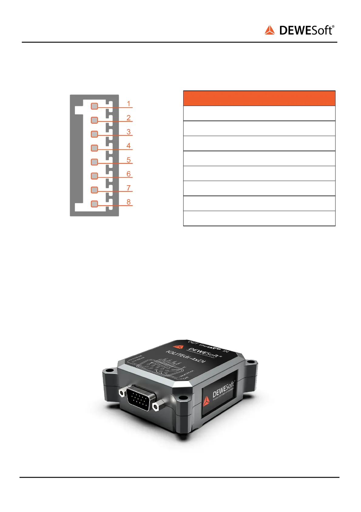
4.7.4. IOLITEi-4xDI
Robust, isolated digital inputs are suitable for reading data off digital sensors as well as for demanding
test automation tasks. Three power supply voltages (5V, 12V and device voltage supply level) available on
the front connector. EtherCAT interface, signal and power over the same cable.
IOLITEi-4xDI module
IOLITE® V22-2 174 / 193

Table of Contents

Questions and Answers:

Question and Answer IconNeed help?

Do you have a question about the DEWESOFT IOLITE V22-2 and is the answer not in the manual?

DEWESOFT IOLITE V22-2 Specifications

General IconGeneral
BrandDEWESOFT
ModelIOLITE V22-2
CategoryNetwork Hardware
LanguageEnglish