Jackson User Manual rev 2.2 www.diamondsystems.com Page 12
3.4 Display
The board offers one HDMI2.1 a/b video output option with audio. The HDMI video output is terminated on a
single port vertical RA type HDMI connector.
3.5 Expansion connector
The board offers an optional Expansion connector for customers who want additional Ethernet, USB3.0 and
USB2.0 options.
The expansion board will have a PCIe Ethernet controller and an Ethernet switch to support additional Ethernet
ports. USB3.0 as well as USB2.0 hub are provided on the expansion board to support additional USB3.0 and
USB2.0 ports. The power to the Expansion board will be provided by the carrier board through the FFC
connector. The variable input power is routed to the FFC connector; 5V and 3.3V are also routed to the FFC
connector.
The PCIex1 lane is muxed with I210 ethernet controller and the expansion connector; one of the two features are
supported by the base board.
Also, the USB3.0 and USB2.0 interfaces on the expansion connector are made available at 2x5 pin header
through a mux and either of the one is supported by the base board.
3.6 Camera
Jackson brings eight MIPI CSI lanes to the board-to-board (B2B) 80-pin connector to plug the camera adapter
card. Two quad-lane camera streams or four dual lane camera streams are supported. Each data lane has a peak
bandwidth of up to 2.5Gbps.
Camera adaptor board supporting 2x 4 CSI lanes over 22 pin connectors can be plugged to 80-pin B2B
connector. Supporting signals like I2C and control signals for the CSI are available at 80-pin connector.
Any custom requirements for cameras can be met using customized camera adapter board. Contact Diamond
Systems for such specific requirements.
Base board provides 2nos M2.5 5mm M/F spacers along with screws to install camera adaptor board at the
bottom side of Jackson base board.
3.7 Serial Ports
Baseboard supports two serial ports. Port 1 supports only RS232 interface, and it is common for all variants. Port
2 supports RS232/RS485/UART 3.3V TTL based on the jumper settings and the board variant.
Port 1 is terminated on 2x5 pin header. Port 2 is terminated on 2x5 pin header and RJ12 connector, either one
can be used at a time.
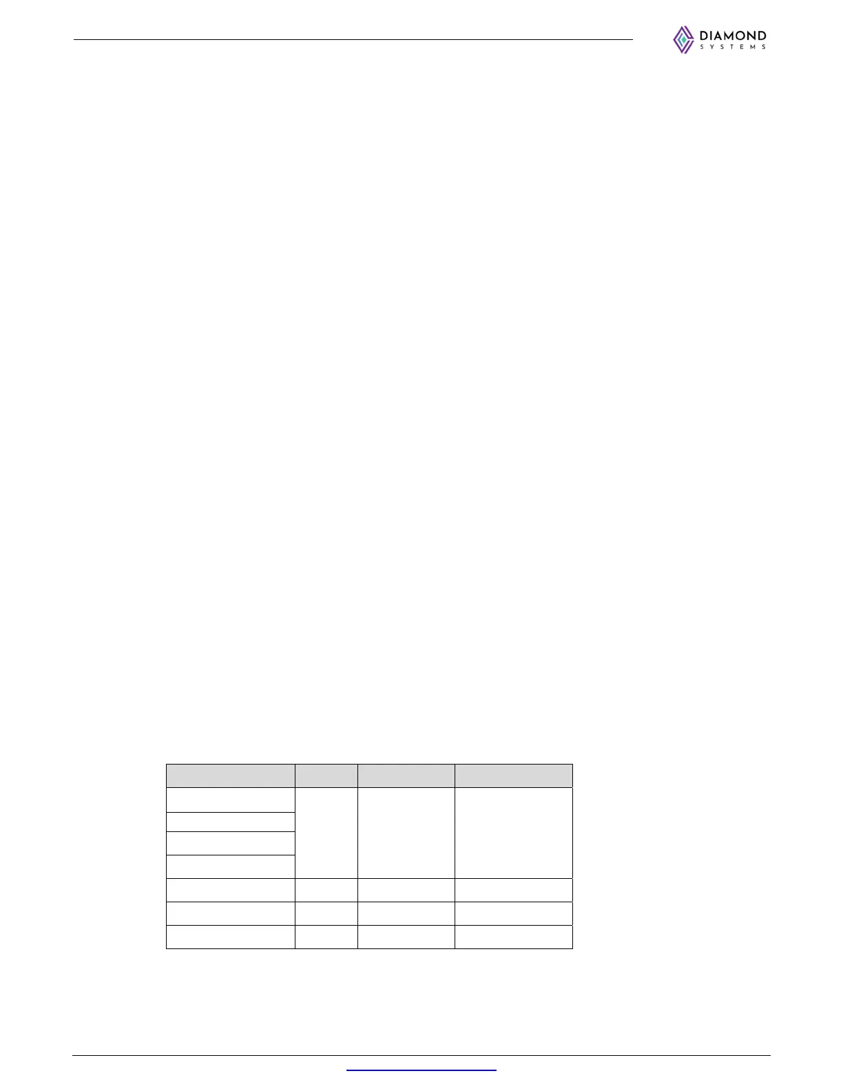
3.8 PCIe Link Routing
The base board utilizes the PCIe lanes from module as per below table:
Lane Port Lane width Peripheral
UPHY0, Lane 4
C4 x4 M.2 PCIe SSD
UPHY0, Lane 5
UPHY0, Lane 6
UPHY0, Lane 7
UPHY0, Lane 3 C1 x1 I210/ Expansion
UPHY2, Lane 0 C7 x1 M.2 E Key
UPHY2, Lane 1 C9 x1 Minicard