Jackson User Manual rev 2.2 www.diamondsystems.com Page 29
7.11 Digital I/O (J10)
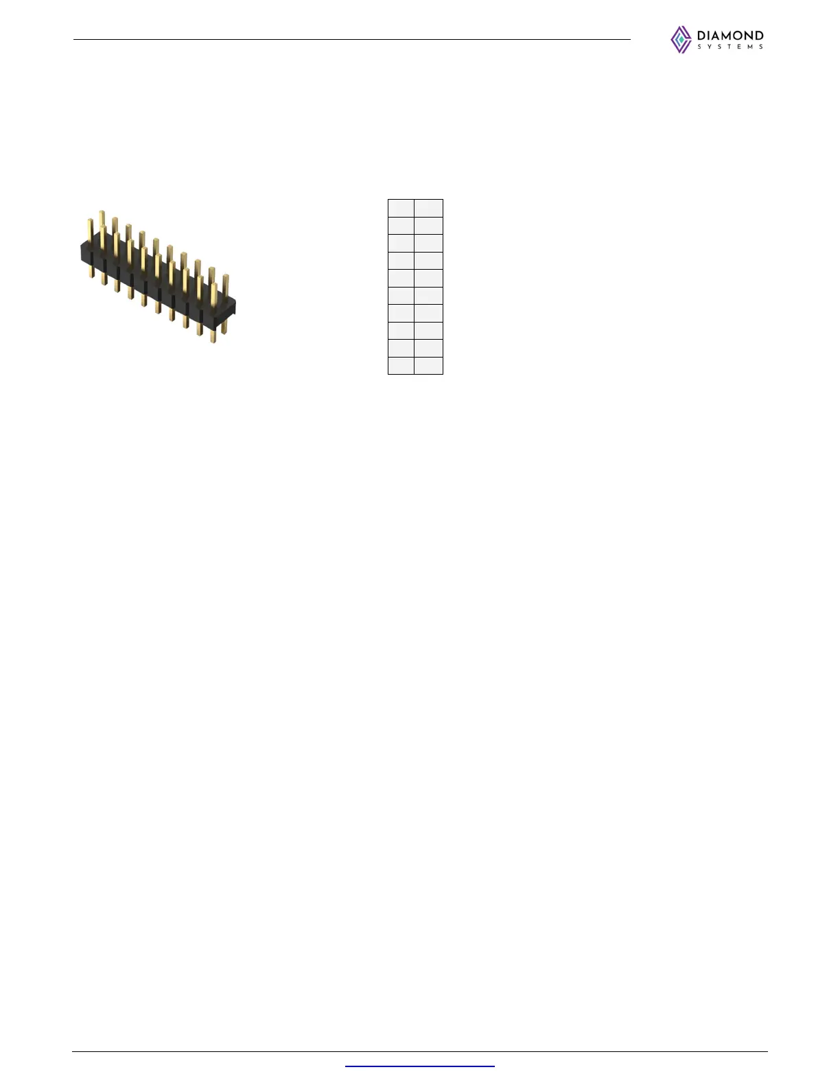
The board provides 16x GPIOs which can be individually programmed for input or output functionalities. The
GPIOs are accessible on a 2x10 header.
JP1 Jumpers are used to select the voltage level (
3.3V/5V) and Pullup/pull down configuration of the DIO. By
default, the DIOs are 3.3 Voltage, pulled down. Refer section 6.1.1 for more information on jumper settings.
DIO_PA0
1 2
DIO_PA1
DIO_PA2
3 4
DIO_PA3
DIO_PA4
5 6
DIO_PA5
DIO_PA6
7 8
V_DIO_PA7
GND
9 10
3.3V / 5V
DIO_PB0
11 12
DIO_PB1
DIO_PB2
13 14
DIO_PB3
DIO_PB4
15 16
DIO_PB5
DIO_PB6
17 18
V_DIO_PB7
GND
19 20
3.3V / 5V
Connector Type: 2x10 2mm Vertical Through-Hole Pin Header, 4mm mating post length
Connector PN: 0877582016
Cable PN: C-20MM-18