Jackson User Manual rev 2.2 www.diamondsystems.com Page 28
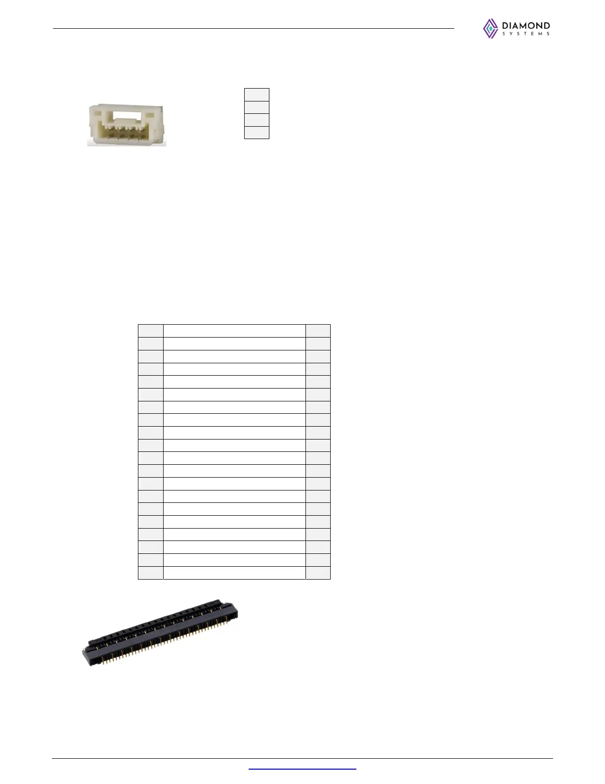
7.9 CAN (J14)
The pinouts for the CAN connector are as shown below:
1
GND CAN
2
CAN_L
3
CAN_H
4
GND CAN
Connector PN: BM04B-GHS-TBT(LF)(SN)(N)
Connector Type: 1x4 1.25mm pitch SMD
Mating Cable PN: 6981182
7.10 Expansion connector (J9)
1x PCIe x1 lane, 1x USB3.0 and 1x USB2.0 ports are routed to a high-speed 40-contact single-sided FFC (flat
flex cable) Expansion connector to support additional Ethernet, USB3.0 and USB2.0 ports. To use the additional
interface, a daughter board expansion is required. For more details about daughter board, contact DSC. Pinout of
the expansion connector is as follows (pinout is shown in 2 columns for compactness).
1 VIN 21
USB2_D1_DB_P
2 VIN 22
GND
3 VIN 23
USB3_TX1_DB_P
4 VIN 24
USB3_TX1_DB_N
5 VIN 25
GND
6 VIN 26
USB3_RX1_DB_P
7 VIN 27
USB3_RX1_DB_N
8 VIN 28
GND
9 PCIE RESET# 29
PCIE1_CLKREQ_NX_3P3#
10 GND 30
DB_PRESENT_3P3#
11 PCIE1_XNX_DB_TX_P 31
GND
12 PCIE1_XNX_DB_TX_N 32
NC
13 GND 33
NC
14 PCIE1_XNX_DB_RX_P 34
NC
15 PCIE1_XNX_DB_RX_N 35
NC
16 GND 36
NC
17 PCIE1_XNX_DB_CLK_P 37
NC
18 PCIE1_XNX_DB_CLK_N 38
GND
19 GND 39
NC
20 USB2_D1_DB_N 40
PCIE_MOD_WAKE_3P3#
Connector type: 40 position 0.5mm pitch FFC latching connector
Connector PN: FH55-40S-0.5SH