Jackson User Manual rev 2.2 www.diamondsystems.com Page 20
6.1 Jumper Selection
The Jumper blocks on the Jackson board can be configured to enable/disable or alter the default signal routing
settings on the circuit, using Jumper shunts.
The following table describes the Jumper Blocks on the baseboard.
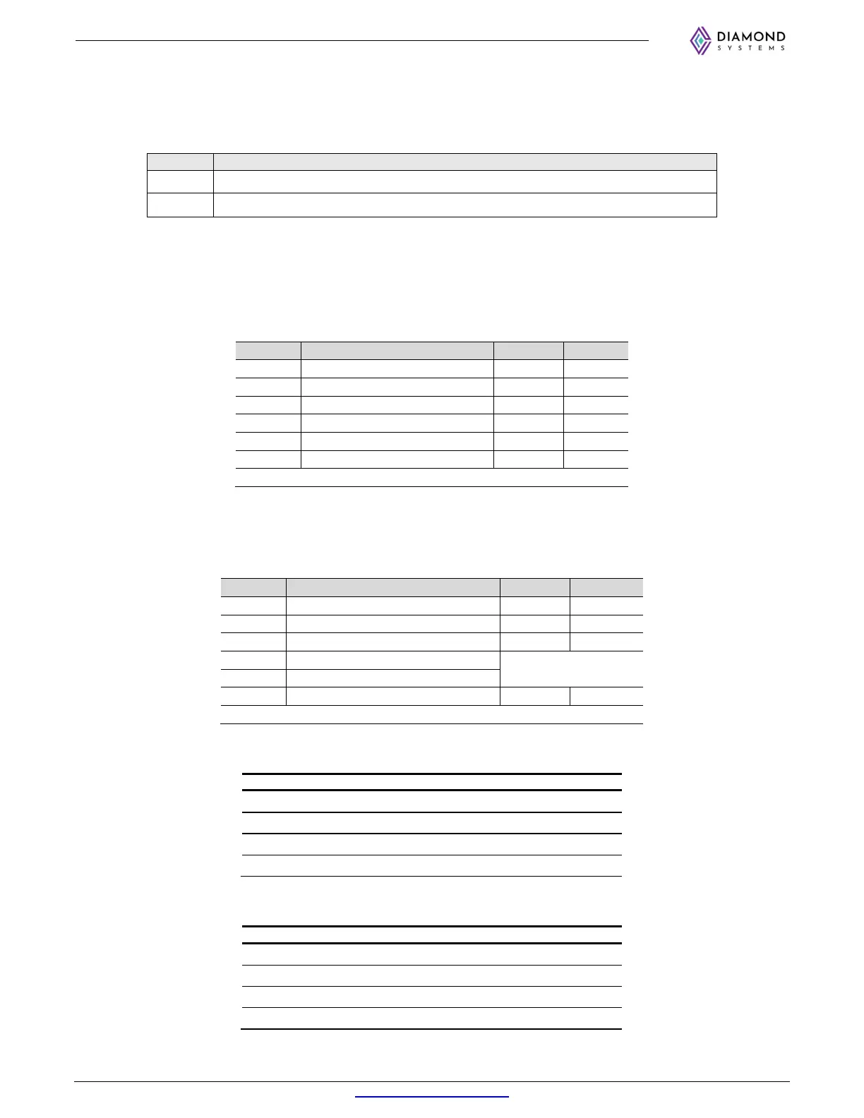
Jumper Description
JP1
DIO voltage selection/DIO push pull selection
JP2
Device/ Host mode selection, Serial mode selection and Termination Enable/Disable
Table 1: Jumper details
6.1.1 JP1 Jumper Configuration
JP1 Jumpers are provided to select the voltage level and Pullup/pull down configuration of the DIO. By
default, the DIOs are 3.3 Voltage pulled down. The configuration is as shown below:
Position Function IN OUT
3P3 DIO Voltage Level *3.3V
5P0 DIO Voltage Level 5V
PDB DIO PORT B Pull Down Enable *Enabled Disabled
PUB DIO PORT B Pull up Enable Enabled Disabled
PDA DIO PORT A Pull Down Enable *Enabled Disabled
PUA DIO PORT A Pull up Enable Enabled Disabled
*Default Mode
6.1.2 JP2 Jumper Configuration
USB1 port of the base board is used as a device in the recovery mode to flash the module and is used as a Host
in normal operation. This selection is achieved by changing the jumper positions on JP2 as tabulated below:
Position Function IN OUT
AUT Auto Power ON Disabled *Enabled
DEV USB2 J4 Bottom Port Device Mode Enabled Disabled
HST USB2 J4 Bottom Port Host Mode *Enabled Disabled
S1 Serial Port Protocol Select1
Refer Table
S0 Serial Port Protocol Select0
TER RS485 Termination Enabled *Disabled
*Default Mode
Serial port 2
Protocol selection Jumper for Standard board (BB01 & BB02):
S1 S
Protocol
OUT OUT *Not Valid (Default)
OUT IN RS232
IN OUT RS485
IN IN Not Valid
Serial port 2
Protocol selection Jumper for Custom board (9242652):
S1 S
Protocol
OUT OUT Not Valid
OUT IN Not Valid
IN OUT Not Valid
IN IN *UART (Default)