Jackson User Manual rev 2.2 www.diamondsystems.com Page 13
3.9 M.2 Socket
The board is equipped with an M.2 M-Key socket to plug-in 2280/2242 x4 PCIe NVMe cards. As there is no
onboard memory on the Orin NX/Nano module, a PCIe SSD must be utilized always.
Base board provides onboard M3 4mm spacer along with a screw to mount M.2 2280 module. M3 4mm spacer
along with 2nos of screws are provided to mount M.2 2242 SSD.
The board supports M.2 E key with x1 PCIe and x1 USB2.0 interfaces which provides additional options for
expansion.
Base board provides onboard M3 2mm spacer along with a screw to mount M.2E key module.
3.10 Minicard
The board offers one full (51mm length) size Minicard socket. Minicard interface supports PCIex1 lane and
USB2.0 x1 interfaces. Nano sim connector is also supported to extend the functionality.
Baseboard provides 2nos onboard M2 4mm spacer and screws on the minicard sockets to mount the modules.
3.11 USB
The board provides access to 3x USB3.2/ USB2.0 ports from the module and 1x USB2.0 port from USB2.0 hub.
1x USB3.2 and 1x USB2.0 ports from the module are muxed between the expansion connector and the header; It
will be available only in the expansion connector on plugging the expansion card.
2x USB3.2 and 1x USB2.0 ports from the module, along with x1 USB2.0 port from the USB2.0 hub is provided on
dual RA stacked USB3.0 connector where x1 USB2.0 port from the module can be used for programming in the
recovery mode. No separate connector is provided for recovery mode.
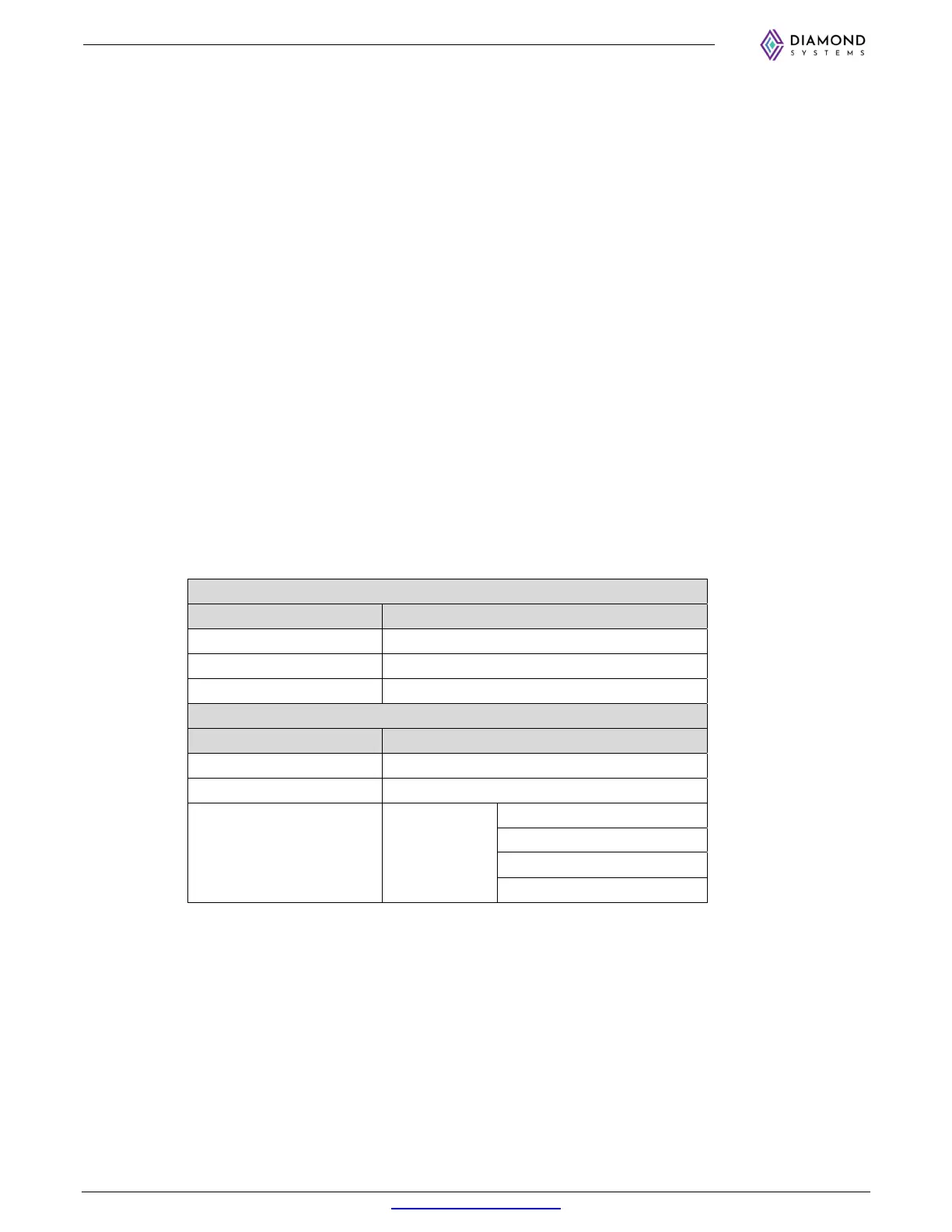
The USB3.2 / USB2.0 port mapping is done as per the below table:
USB3.2 Ports
Port from Module Port Termination
Port 0 USB3 Connector 1
Port 1 Expansion Connector / Header
Port 2 USB3 Connector 2
USB2.0 Ports
Port from Module Port Termination
Port 0 (Recovery) USB3 Connector 1
Port 1 Expansion Connector / Header
Port 2
USB 2.0 HUB
(1:4)
M.2 E Key
Minicard Socket
USB3 Connector 2
1x5 Header
3.12 Digital I/O
The board provides 16x digital I/O lines, which are individually configurable as an output or input. Digital I/O lines
are realized using an I2C GPIO expander. The I2C control for the expander is directly fed from the module. This
I2C is 3.3V compliant, hence no level translation is necessary. This expander device is accessible on the I2C
address 0x22.The I/O lines are made available on a 2x10 header.
3.13 Controller Area Network (CAN)
The base board is equipped with a CAN interface. The interface can be realized with a non-isolated
TJA1042T,118 transceiver or with an isolated ADM3053BRWZ transceiver, available as assembly options. By
default, the CAN is realized with the non-isolated TJA1042T,118 transceiver.