12/ INSTALLATION
OPERATOR'S MANUAL
Dj SEED MANAGER® SE PLANTER MONITOR
BENCHMARK Series® 11001-1218-200112 Rev A
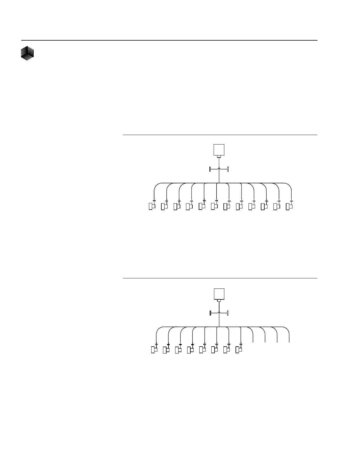
When connecting sensors to the Material Flow Modules, the following requirement
must be observed:
1. All seed sensors installed on a Material Flow Module must be connected sequential-
ly starting with Row 1 as shown below.
Row
1
Row
2
Row
3
Row
5
Row
4
Row
6
Row
7
Row
8
Row
9
Row
11
Row
10
Row
12
RS-485 IN RS-485 OUT
In the event that not all row inputs on a module will be used, the unused row inputs
must be last as shown in the following eight row module setup:
Row
1
Row
2
Row
3
Row
5
Row
4
Row
6
Row
7
Row
8
Row
9
Row
11
Row
10
Row
12
RS-485 IN RS-485 OUT
CORRECT
CORRECT
Figure 6F
Correct Install
Figure 6G
Correct Install

 Loading...