22
160XT 180XT 210XT
8 OPERATION OF THE SAFETY DEVICES
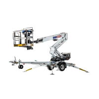
1. Support outriggers (Fig. A)
The safety limit switch RK3 prevents the operation of the outriggers and the driving
device when the boom is not resting on the transport support. The switch is located on
the tow-bar at the transport support.
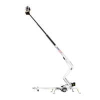
2. Lifting the boom (Fig. B)
The lift’s all support outriggers must be in the support position before the boom is lifted.
Make sure that the wheels are off the ground.
The safety limit switches RK11, RK12, RK13 and RK14 are located on the support
outriggers.
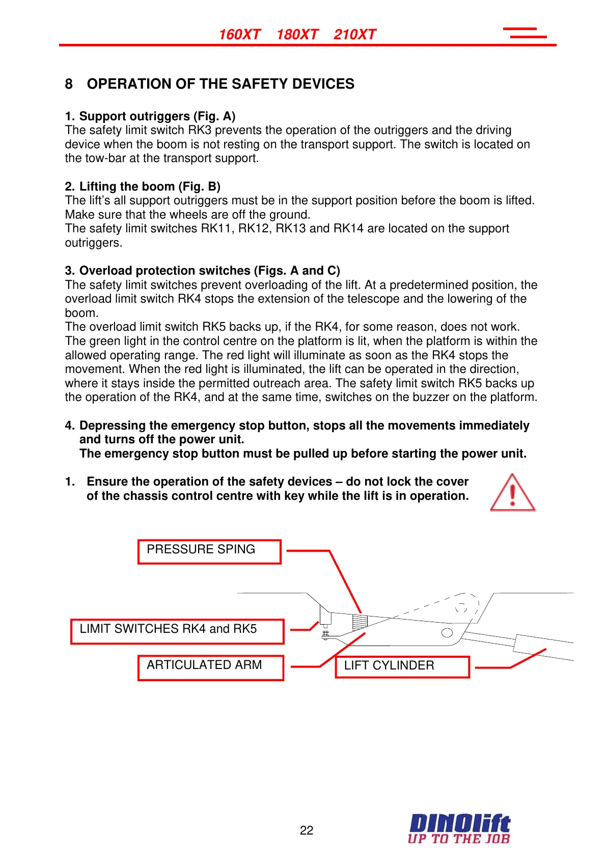
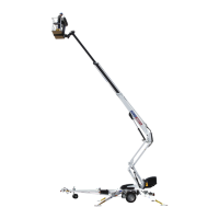
3. Overload protection switches (Figs. A and C)
The safety limit switches prevent overloading of the lift. At a predetermined position, the
overload limit switch RK4 stops the extension of the telescope and the lowering of the
boom.
The overload limit switch RK5 backs up, if the RK4, for some reason, does not work.
The green light in the control centre on the platform is lit, when the platform is within the
allowed operating range. The red light will illuminate as soon as the RK4 stops the
movement. When the red light is illuminated, the lift can be operated in the direction,
where it stays inside the permitted outreach area. The safety limit switch RK5 backs up
the operation of the RK4, and at the same time, switches on the buzzer on the platform.
4. Depressing the emergency stop button, stops all the movements immediately
and turns off the power unit.
The emergency stop button must be pulled up before starting the power unit.
1. Ensure the operation of the safety devices – do not lock the cover
of the chassis control centre with key while the lift is in operation.
LIMIT SWITCHES RK4 and RK5
PRESSURE SPING
LIFT CYLINDER
ARTICULATED ARM
Courtesy of Crane.Market