Simga2N Traction Advanced Manual– V1.3 Page 26 (166) ©2021 DMC GmbH Herten Germany
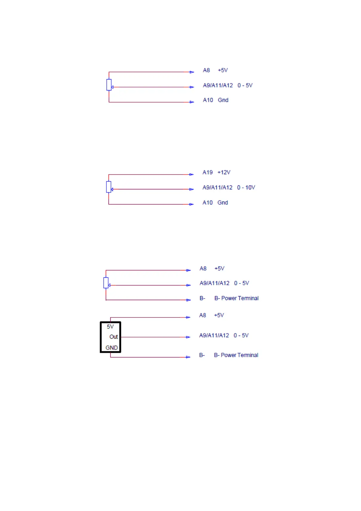
Wiring between +5V and Gnd Pot Supply
This option consists in connecting one terminal of the analog potentiometer to “Pin A8 Analogue supply 5V” and the
other to “Pin A10 Analogue supply 0V”.
In this case the potentiometer has wire-off detection capability at both terminals. By means of parameter “M2-6
Accelerator supply wire off detection ”SplyWrOf”” the user can set whether he wants detection on “Pin A8 Analogue
supply 5V”, “Pin A10 Analogue supply 0V” or both (Respectively setting the parameter to 2, 1 or 3). The suggestion in
this case is to enable the wire-off detection on “Pin A10 Analogue supply 0V” since it has higher sensitivity.
Wiring between +12V and Gnd Pot Supply
This option consists in connecting one terminal of the analog potentiometer to “Pin A19 Supply 12V -- 70mA max.” and
the other to “Pin A10 Analogue supply 0V”.
In this case the potentiometer has wire-off detection capability at “Pin A10 Analogue supply 0V”. The wire-off detection
can be enabled by setting parameter “M2-6 Accelerator supply wire off detection ”SplyWrOf”” to 1.
Wiring between +5V and B- power terminal
This option consists in connecting one terminal of the analog potentiometer to “Pin A8 Analogue supply 5V” and the
other to the negative power terminal of the battery.
Notice that in this case also an electronic potentiometer or sensor can be wired.
In this case the analog/digital potentiometer has wire-off detection capability at “Pin A8 Analogue supply 5V”. The wire-
off detection can be enabled by setting parameter “M2-6 Accelerator supply wire off detection ”SplyWrOf”” to 2.