Dobot CR Series User Guide
Issue V1.1 (2023-04-27) User Guide Copyright © Yuejiang Technology Co., Ltd.
24
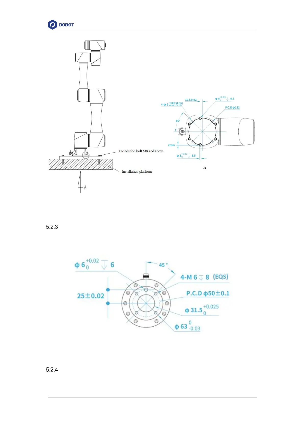
Figure 5.6 CR5 base installation dimensions
CR5 flange dimensions
The end flanges of CR series robot arms are all in the same size. The flange design conforms
to ISO 9409-1.
Figure 5.7 End flange dimensions
CR5 load curve
In the load curve, the coordinate origin is the center of the end flange, and X, Y represent the