Dobot CR Series User Guide
Issue V1.1 (2023-04-27) User Guide Copyright © Yuejiang Technology Co., Ltd.
54
Figure 7.3 Controller installation space requirement
End tool installation
The end flange of the robot arm has four M6 threaded holes, which can fix the tool to the end
of the robot arm. In order to accurately adjust the position of the tool, you can also use the
reserved Φ6 positioning hole. The end flanges of CR series robot arms are in the same size. For
detailed dimensions, refer to 5 Mechanical Specifications.
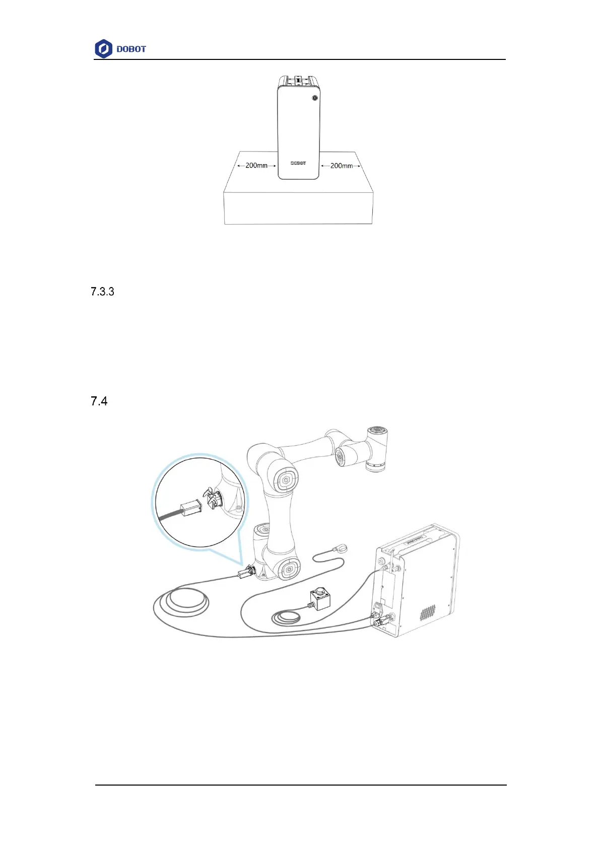
Wiring
Figure 7.4 Wiring diagram
1. Connect the controller to robot arm through a heavy-duty cable. When you plug the heavy-
duty connector into the heavy-duty socket, fix the buckle of the heavy-duty connector.
2. Plug the emergency stop switch cable to the emergency stop switch interface. When
connecting, align the red point on the connector with the red point on the interface.
3. Plug the wireless receiver into the USB interface.