Dobot CR Series User Guide
Issue V1.1 (2023-04-27) User Guide Copyright © Yuejiang Technology Co., Ltd.
53
Robot installation
Robot arm installation
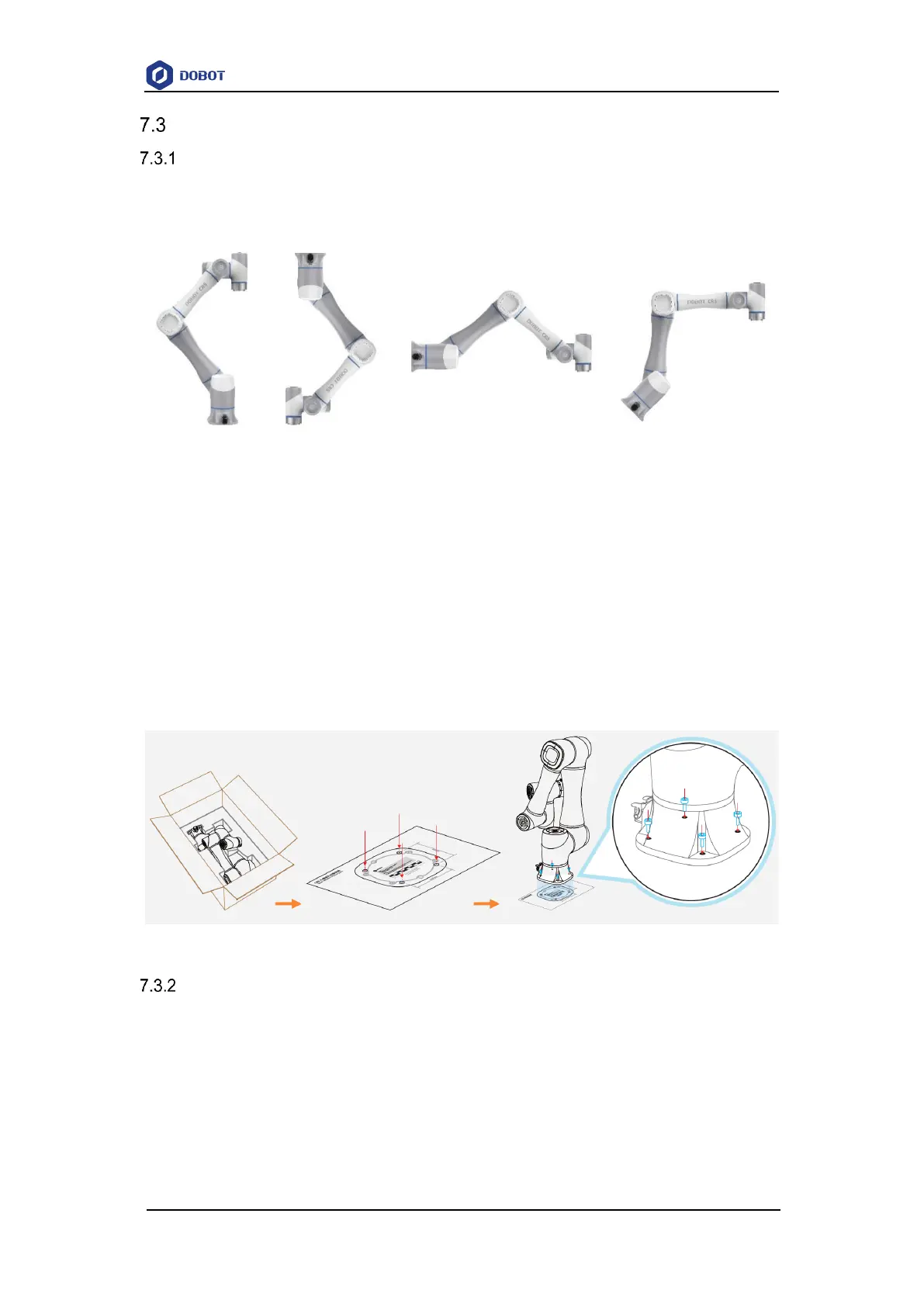
CR robot arm supports 360° installation at any angle. Figure 7.1 shows several typical
installation postures.
Figure 7.1 CR robot installation posture
The installation platform of the robot arm should be stable enough to withstand at least 10
times the maximum torque of the J1 joint, and at least 5 times the weight of the robot arm.
If the robot arm is installed on a linear axis or a moving platform, the acceleration of the
platform should be low, and high acceleration may trigger the robotic arm's collision detection
mechanism and cause the robotic arm to stop.
Position the mounting holes on the installation platform according to the installation size of the
robot base. Fix the robot arm base on the surface using bolts (4 M6 bolts for CR3, and 4 M8 bolts
for other models). You can refer to 5 Mechanical Specifications for the specific dimensions of the
robot base.
Figure 7.2 Base installation
Controller installation
Place the controller on a stable platform outside the working range of the robot arm, and reserve
enough space for wiring and operation. Please leave at least 200 mm gap on the left and right sides
and keep the vent unblocked to ensure enough space for heat dissipation. Place the control cabinet
on a solid and flat plane outside the working space of the robotic arm, and reserve enough cable
wiring space and operation space. A space of 200mm should be reserved on the left and right sides,
and the trend will not be blocked to ensure sufficient heat dissipation space.