Dobot CR Series User Guide
Issue V1.1 (2023-04-27) User Guide Copyright © Yuejiang Technology Co., Ltd.
35
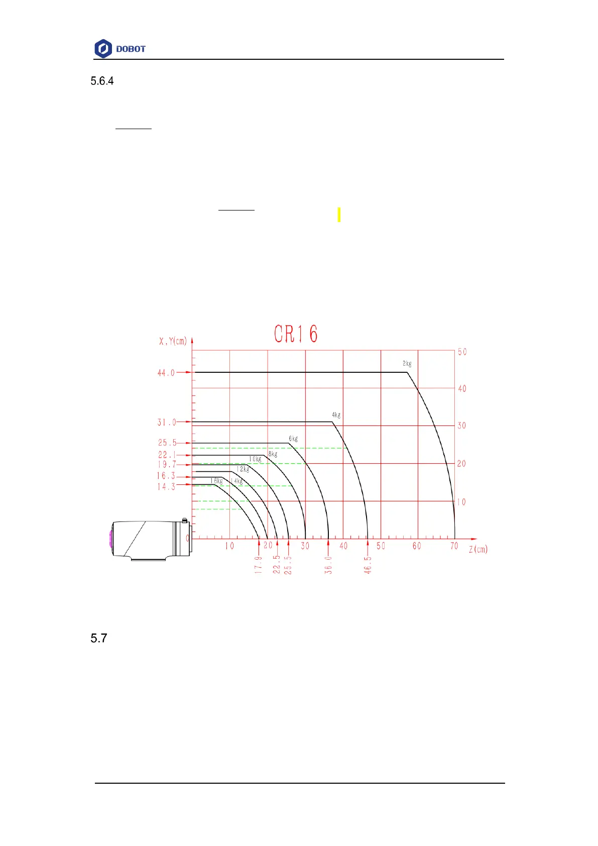
CR16 load curve
In the load curve, the coordinate origin is the center of the end flange, and X, Y represent the
distance between the gravity center of load and the robot flange in X and Y directions. According to
r =
√
𝑋
2
+ 𝑌
2
, the value r corresponds to the vertical coordinate X, Y[cm] of the load curve, and
the abscissa Z[cm] represents the distance from the gravity center of the load to the robot flange in
Z direction. You can determine the working condition of the robot according to the statistical results.
For example, if the load is 2.8kg, X = 6cm, Y = 8cm, Z = 5cm, and you can get r = 10cm. The steps
for judgement are as follows:
According to r =
√
𝑋
2
+ 𝑌
2
, calculate r = 10cm.
Select the corresponding curve according to the weight of the load. As the load is 2.8kg,
you need to find the curve of 3kg correspondingly.
Determine a point according to the r and Z coordinates, and compare the positional
relationship between the point and the 3kg curve to judge the working condition. If the
point is below the curve, the model is proper, otherwise you need to select other models.
Figure 5.22 CR16 load curve
Controller dimensions
The dimensions of CC162 controller are shown in Figure 5.23.