Dobot CR Series User Guide
Issue V1.1 (2023-04-27) User Guide Copyright © Yuejiang Technology Co., Ltd.
37
Electrical Features
Controller interface
Overview
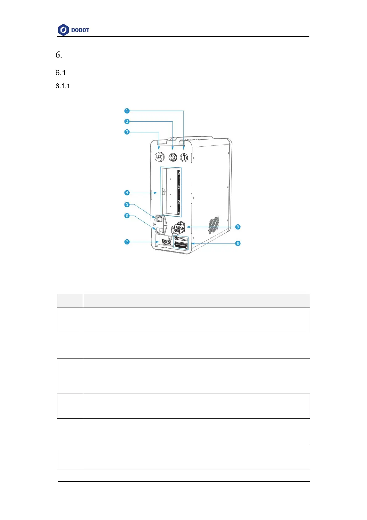
The interfaces of the controller are shown in Figure 6.1.
Figure 6.1 Controller electrical interfaces
Table 6.1 Interface panel description
USB interface
For connecting to WiFi module
SmartPendant and emergency stop switch interface
For connecting to SmartPendant (optional) or emergency stop switch
LAN interface (default address: 192.168.5.1)
For connecting to PC (Used for debugging), or other external network equipment of TCP/IP or
Modbus TCP protocol
General I/O interface
See 6.1.2 General I/O interface panel
Power switch of controller
For powering on/off the controller
Power interface
For accessing single-phase 1100/220V AC power supply