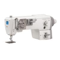
7.4.5 Selecting output elements
This program checks the function of the output elements.
One (single mode) or several (multi-mode) output elements can be
tested simultaneously.
Caution: danger of injury !
Do not reach into the machine while it is running and the function
of the output elements is under test.
–
Press Enter to run the test program.
–
Use the decimal keypad to select between single mode and
multi-mode .
1 = single mode: only one output element
is tested.
2 = multi-mode: a group of output elements
is tested.
–
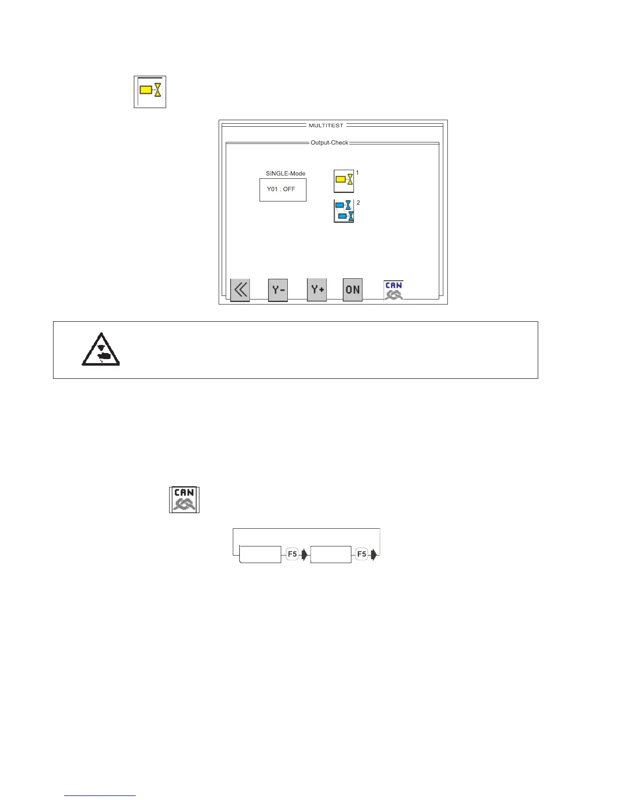
Press the “F5” key to switch from DACIII control to the output
elements of the CAN node.
DACIII = maximum of 16 outputs from YC001 to YC016
CAN 1 = maximum of 56 outputs from YC101 to YC156
–
Enter the code number of the required output element with “F3”
(forwards) or “F2” (backwards).
The code numbers are the abbreviations used in the circuit
diagram (see tables below).
–
The display shows the switching status (ON/OFF) of the output
element selected.
–
Switch the selected output element on (ON) and off (OFF)by
pressing function key “F4”.
–
To leave the test program press function key F1.
78

 Loading...