Aligning the needle bar linkage
Service Instructions 667 - 00.0 - 04/2016 45
9.2 Aligning the needle bar linkage in the sewing direction
Cover
• Valve cover ( p. 13)
• Tilt the machine head ( p. 10)
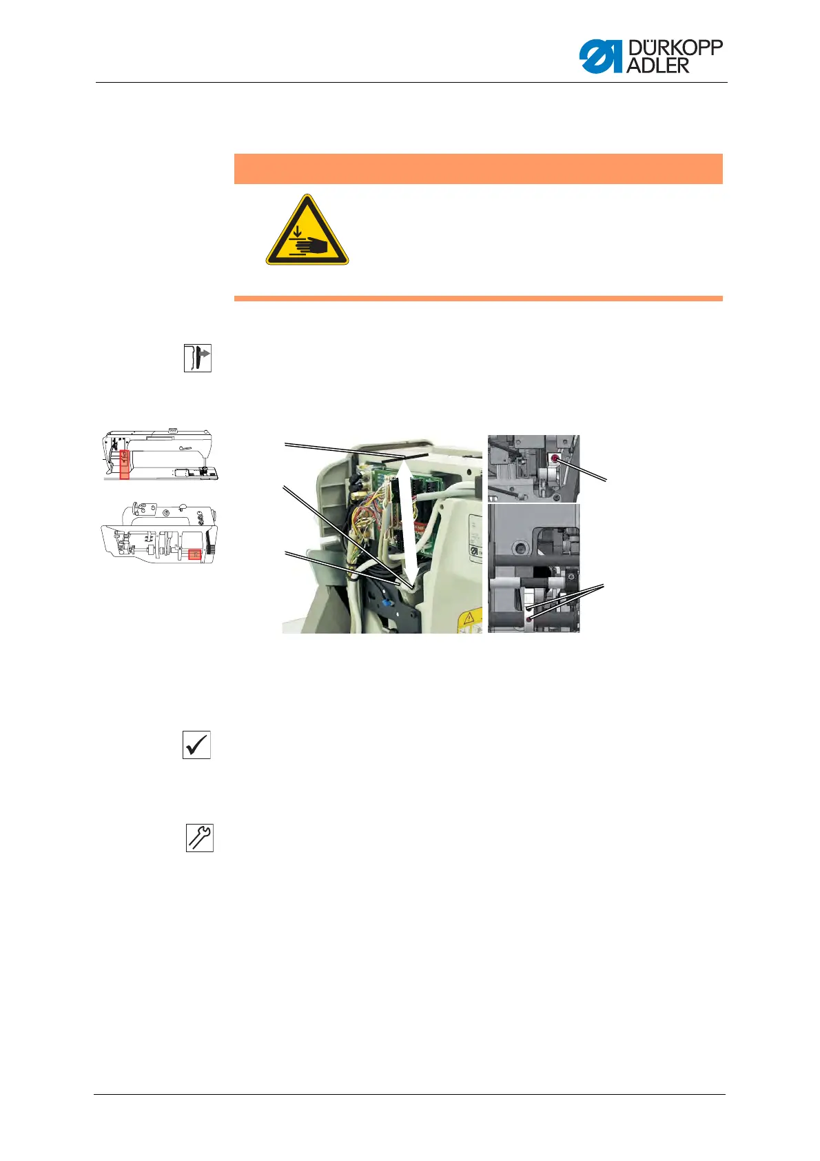
Fig. 29: Aligning the needle bar linkage in the sewing direction
Proper setting
Stitch length adjusting wheels to 0.
The lever (3) is positioned such that the distance from the surface of
the arm (1) to the middle of the bolt (2) is 126.6 mm.
To align the needle bar linkage in the sewing direction:
1. Position the lower stitch length adjusting wheel to 0.
2. Position the upper stitch length adjusting wheel to 0.
3. Loosen the threaded pins (4).
4. Loosen the screw (5).
5. Position the lever (3).
6. Tighten the threaded pins (4).
7. Tighten the screw (5).
WARNING
Risk of injury from moving parts!
Crushing possible.
Switch off the machine before you check and set
the position of the needle bar linkage in the sewing
direction.
126,6 mm
(1) - Arm surface
(2) - Center of bolt
(3) - Lever
(4) - Threaded pins
(5) - Screw
①
③
②
④
⑤