Eaton 93PR 15-80 kW UPS
Installation and Operation Manual
72
Copyright © 2022 Eaton Corporation plc. All rights reserved.
6.6. Transfer the UPS from Double Conversion Mode to Maintenance Bypass Mode
The operation of the internal MBS is allowed for trained personnel only who is familiar with the UPS
behavior and functions. The full UPS wiring diagram with a MBS switch is presented in the installation
instructions.
CAUTION
The integral MBS and Static Bypass need to supplied by the same source.
Maintenance bypass input
Static bypass input
Rectifier input
Maintenance bypass switch (MBS)
Output
Maintenance bypass input
Static bypass input
Rectifier input
Maintenance bypass switch (MBS)
Output
Output switch
Maintenance bypass input
Static bypass input
Rectifier input
Maintenance bypass switch (MBS)
Output
Output switch
Maintenance bypass input
Static bypass input
Rectifier input
Maintenance bypass switch (MBS)
Output
Output switch
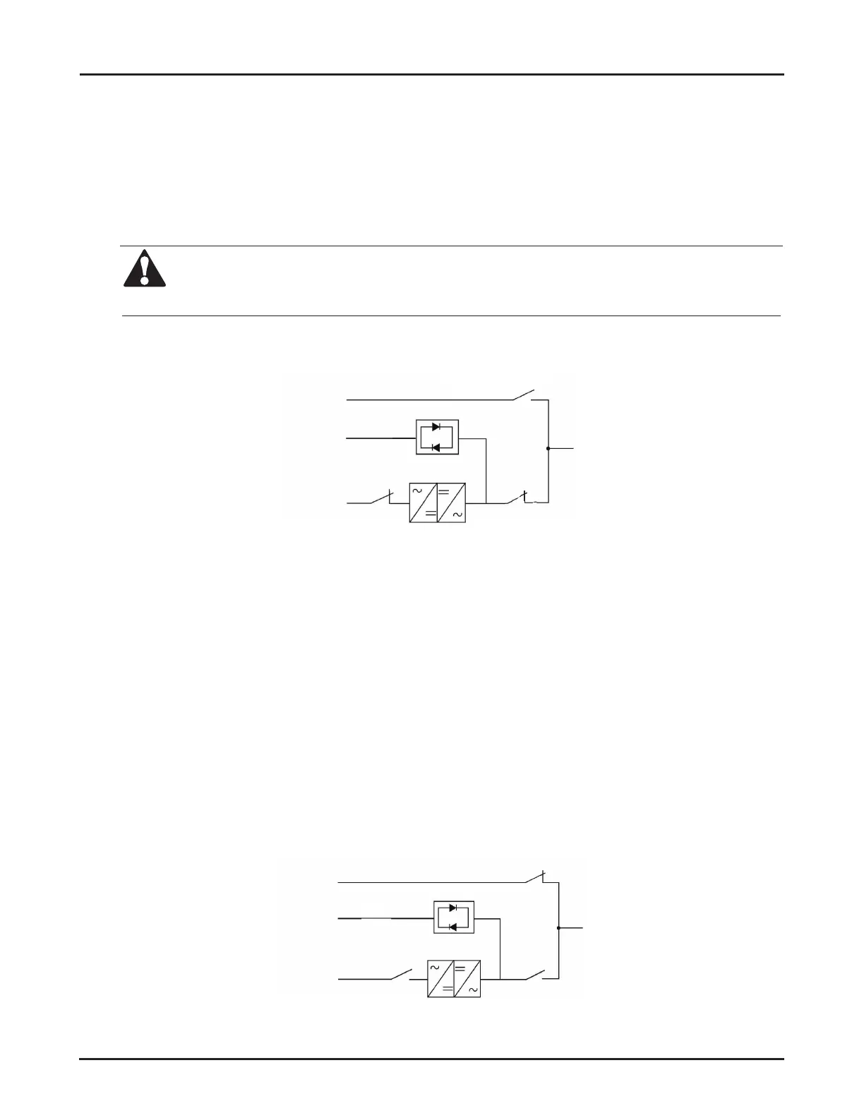
Figure 6-37: Switch status in online mode
1. In terms of switching from “Online Mode” to “Bypass Mode”, please see Section
6.3.3
Switch from
“Online” mode to “Bypass” mode for the method;
2. Close the maintenance bypass switch;
3. Shut down the system by the method presented in Section
6.3.7
“System Shutdown”;
4. Open the input switch to cut off the UPS rectier input;
5. Open the output switch to cut off the UPS inverter output;
6. Open the bypass switch to cut off the UPS bypass input;
7. Open the external battery switches (including battery N-wire switch).
UPS in “Maintenance Bypass Mode”
Maintenance bypass input
Static bypass input
Rectifier input
Maintenance bypass switch (MBS)
Output
Maintenance bypass input
Static bypass input
Rectifier input
Maintenance bypass switch (MBS)
Output
Output switch
Maintenance bypass input
Static bypass input
Rectifier input
Maintenance bypass switch (MBS)
Output
Output switch
Maintenance bypass input
Static bypass input
Rectifier input
Maintenance bypass switch (MBS)
Output
Output switch
Output switch
Figure 6-38: Switch status in maintenance bypass mode

 Loading...


