9
Copyright © 2022 Eaton Corporation plc. All rights reserved.
2.1. Internal structure of UPS system
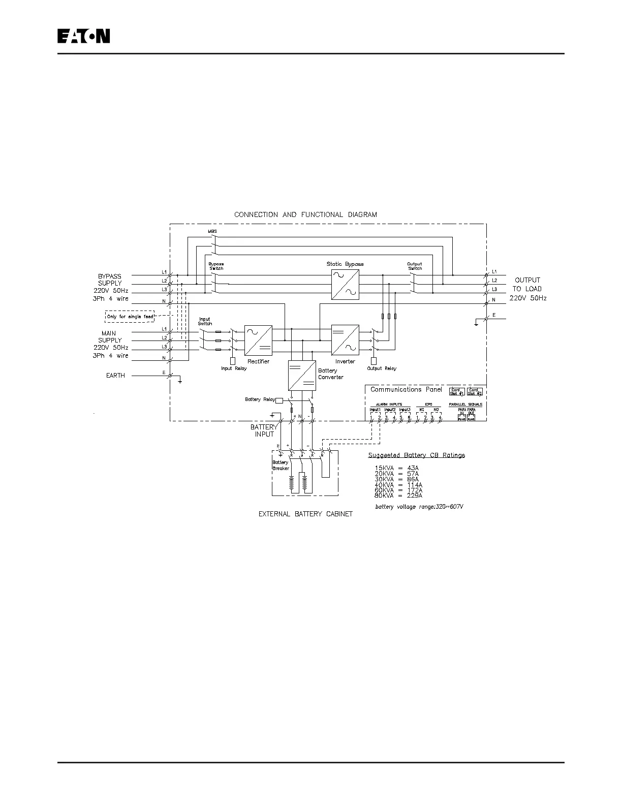
The 93PR UPS is comprised of power module, one input switch, one bypass switch, one output switch
and one internal MBS. The UPS contains no internal battery.
Please see
Figure 2-4
.for the structure of the UPS cabinet.
The power module includes rectier, battery converter, inverter, and static bypass.
Figure 2-4: 93PR UPS Wiring Diagram
If AC power supply is interrupted or exceeds the technical parameters provided in
Chapter 8
, the UPS
will use the standby battery to supply power to the load. The power supply from the battery will endure
a specied time or until the AC power supply recovers. In the case of long-time interruption of power
supply, the UPS will allow switching to another power system (e.g., generator) or shut down the loads in
sequence.

 Loading...


