1 Device series DS7
1.4 Description
14 DS7 Soft starter 09/16 MN03901001Z-EN www.eaton.com
1.4.2 DS7-34D…
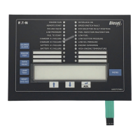
The following drawing shows a DS7-34D…
soft starter with a SmartWire-DT
connection (hereafter referred to with the abbreviation DS7-SWD) of size 2.
Figure 4: Description of the DS7-34D…-D soft starter
a Fixing holes (screw fastening)
b Data interface for PKE32-COM
c Cutout for mounting on mounting rail (DIN EN 50022-35)
d Device fan (mounting space on rear)
e Connection terminals of the power section, motor connection (2T1, 4T2, 6T3)
f Control signal terminals
g Potentiometer (U-Start, t-Start, t-Stop)
h Light-emitting diodes (RUN, Error): DS7 diagnostic LEDs
i 1-0-A switch
j Connection for SmartWire-DT external device plug
k LED: SmartWire-DT diagnostic LED
l Connection terminals of the power section, mains voltage (1L1, 3L2, 3L3)
→
The SmartWire-DT external device plug with an adapted
SmartWire-DT ribbon cable is connected to the DS7-SWD soft
starter via connection ⑩.
For detailed instructions on how to use the SmartWire-DT
external device plug (SWD4-8SF2-5) with the 8-pin SmartWire-DT
cable, refer to the “Setting up SWD4-8SF2-5 external device
plugs” section in manual MN05006002Z-EN,
“SmartWire-DT - The System.”
→
SmartWire-DT diagnostic LED ⑪ shows the communication
status, the status of the DS7-SWD soft starter, and the
switching command via the SmartWire-DT system.
For more information on the SmartWire-DT diagnostic LED,
refer to → section 8.10.4, “SmartWire-DT diagnostic LEDs”,
page 214.