10.4.1 CAN Bus Assignment
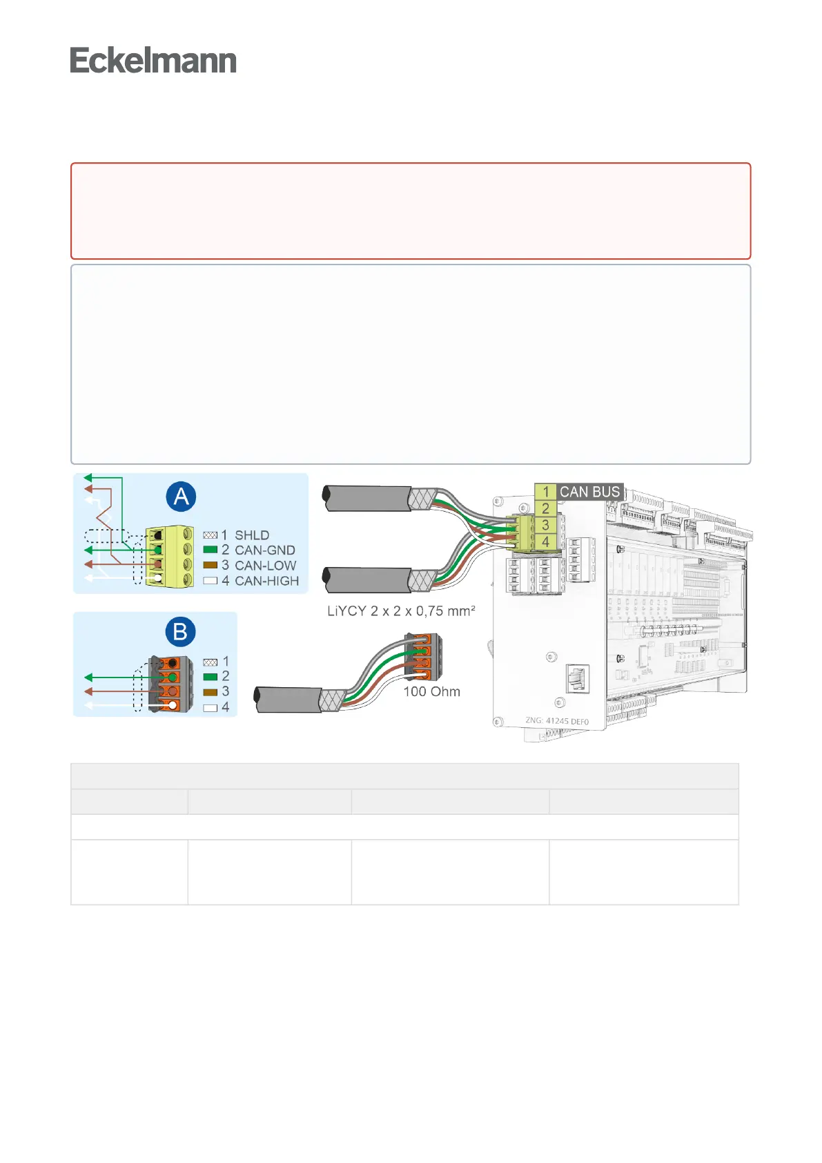
CAN BUS on the base module
Description Terminal No. Connection Wire colour
Standard, for connection to the E*LDS system
CAN BUS 1
2
3
4
SHIELD
CAN-GND (Ground)
CAN-LOW
CAN-HIGH
shield
green
brown
white
For details, see chapter Setting the CAN bus address using decade switch S2.
DANGER
Warning about dangerous electrical voltage! Danger to life - Danger of electric shock! BEFORE
connecting and disconnecting, it must be ensured that no voltage is present at all connections of the
controller.
ATTENTION
All CAN bus supply lines must be shielded (cable type: LiYCY 2x2x0.75 mm
2
). As a general rule, care
should be taken to ensure that signal cables and cables carrying mains voltage are routed in separate
cable channels Maximum length of the cable: 500 m.
Wiring Variant A: Device is a node in a CAN bus segment with other nodes before and after this, no
terminating resistor required.
Wiring Variant B: Device is at the start / end of a CAN bus segment, a100Ohmterminatingresistor
is required (part number KGLCANTERM).
ForfurtherdetailsabouttheCANbus,seeoperatingmanual"E*LDS Basics, Safety Instructions, CAN
Bus & Modbus".