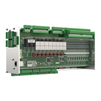
9.3.1 Settings using DIP switch S1
There are two types of coding switches on DIP switch S1:
1. Coding switches 1..4 - Freely programmable in CODESYS.
These are read in during the runtime and act on the controller immediately after adjustment. The coding
switches are freely available to the programmer of the application. The programmer defines the meaning of the
coding switches, how they should be used.
Coding switches 1..4 Switch position Function
ON
Freely programmable
OFF
2. Coding switches 5..7 - Hard-coded into the firmware of the controller.
These do not take effect until after restart, i.e. not until after a short interruption of the power supply of the
controller.
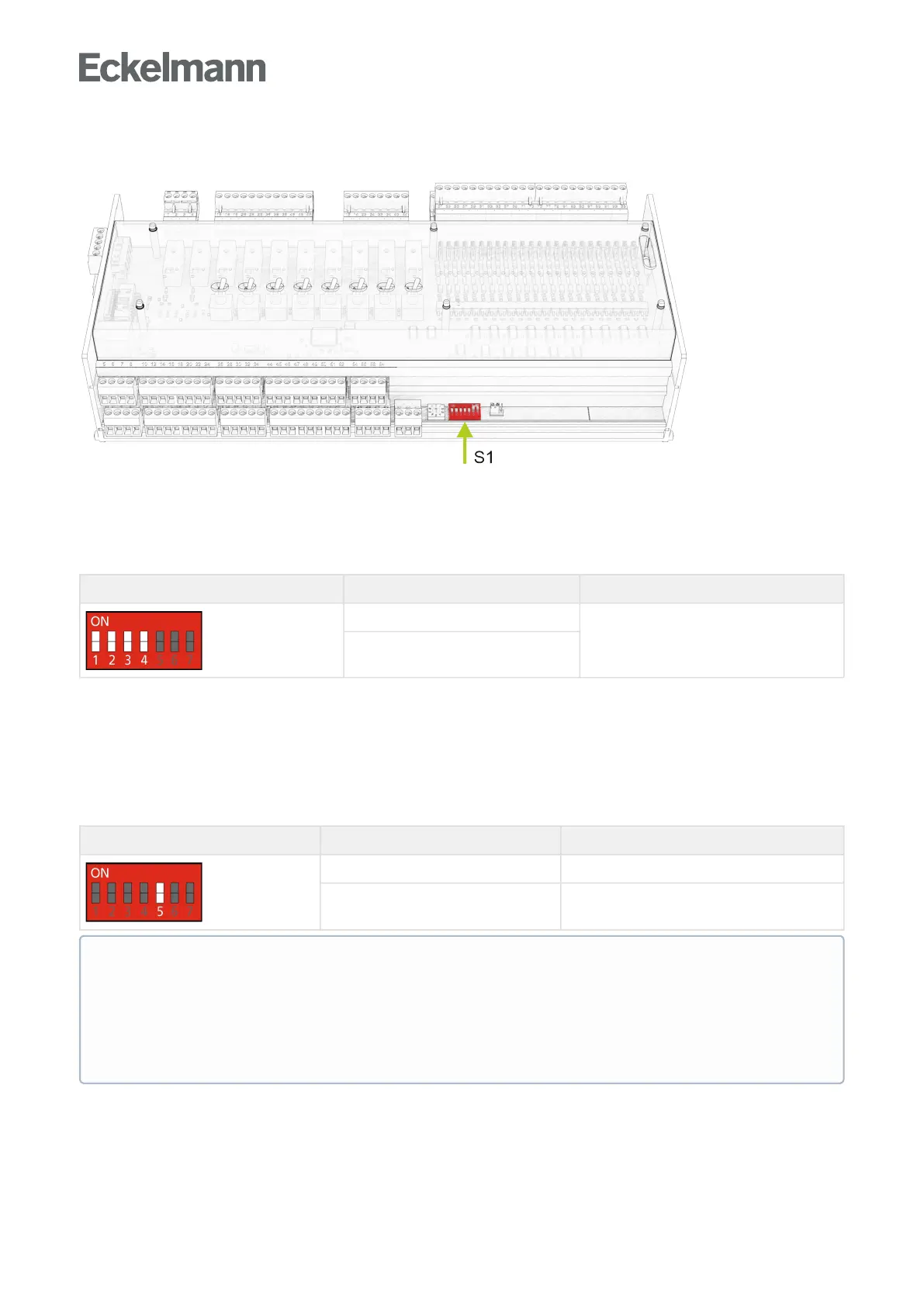
Coding switch 5
Coding switch 5 sets the transfer rate on the CAN bus. Up to now, a transmission rate of only 50 kbit/s was
possible on the CAN bus (factory setting). By flipping the coding switch to "ON" you get 5 times the transfer rate
(250kbit/s).TheHighSpeedmodeoftheCombiGatewayprovidesthistransferrate
Codingswitch5 Switch position Function
ON 250 kbit/s (High Speed)
OFF 50 kbit/s (factory setting)
ATTENTION - ONLY CI 3x00
If the setting is incorrect, no communication can be established with the CAN bus. When using the high
speed mode, the store computer CI 3x00 must be configured accordingly. The following requirements
must be met:
The store computer must have the firmware V5.0 or higher and the parameter "CAN Bus Fast" (menu
6-1-1) must be set to Yes.