9.3.4 Configuration of the analogue inputs and outputs
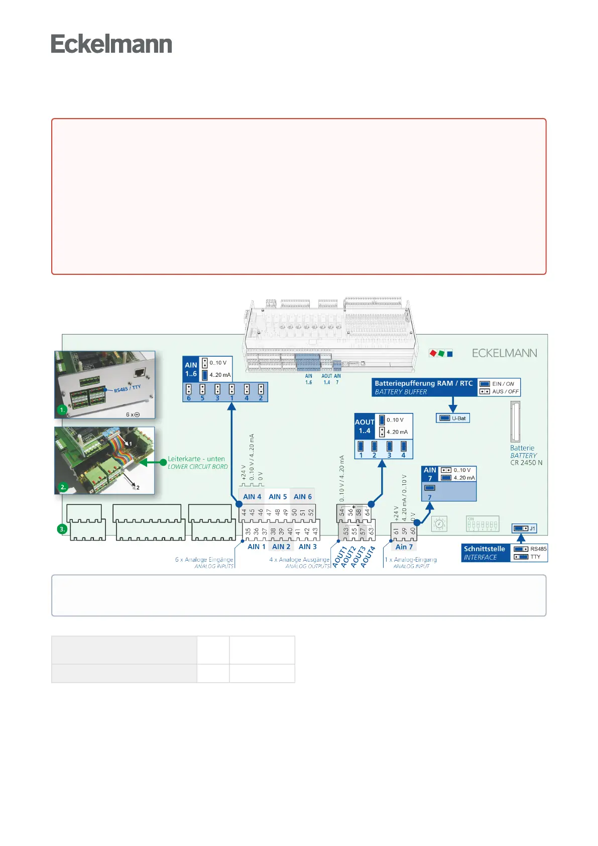
The analogue inputs and outputs can be configured using jumpers on the bottom circuit board of the controller.
The analogue inputs and outputs are configured at the factory as follows:
Analogue inputs (AIN) 1..6
7
0..10 V
4..20 mA
Analogue outputs (AOUT) 1..4 0..10 V
DANGER
Warningaboutdangerouselectricalvoltage!Dangertolife-Dangerofelectricshock!
Before opening the case, it is essential to disconnect the device from the power supply! All plug
connectors may only be inserted and removed when the power supply is disconnected. For details
about opening the case, see chapter Replacing the battery.
Reconfiguration of the analogue inputs and outputs is only necessary if settings different from the
delivered condition have to be made, e.g. if analogue signals with 4..20 mA signal existing in the
system should be used. A reconfiguration or any opening of the controller must only be performed by
trained personnel or at the factory by the manufacturer. Incorrect handling can result in damage and
impairment of the controller functions!
After opening, the device must be subjected to an insulation test!
Practical tip: For better interference immunity, the analogue inputs should be configured for 4..20 mA
current for long cable lengths.