•
•
•
•
•
Configuration of the digital inputs
Ju
mp
er
Voltag
e
Function / conditions Diagram
230 V
AC
(factor
y
setting
)
Only AC voltage signals are supported.
The N conductor must be connected on the terminal level (50..72), here using the
example of terminals 50..62 with jumper.
-
PE For mixed operation of the voltage levels! Low voltage (230 V AC) and safety extra-
low voltage (24 V AC/DC) must be separated by a digital input connected to PE, here
using the example of terminals 64/65.
-
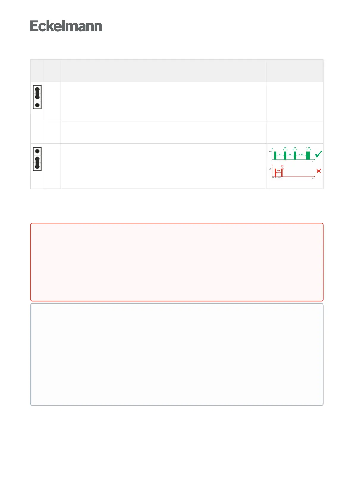
24 V
AC/DC
AC and DC low voltage signals are detected and evaluated.
Exception: acquisition of 24 V DC counter pulses (S0 interface)
To count S0 pulses, these must be at least 95 ms apart, otherwise faster pulse
sequences will not be detected. The pulse width must be at least 30 ms.
GNDof24VDC must be connected on the terminal level (50..72), here using the
example of terminals 66..72 with jumper.
For details about the assignment, see chapter Assignment of the digital inputs - 230 V AC / 24 V AC/DC.
10.2.3 Assignment of the relay outputs - 230 V AC / 24 V AC/DC
DANGER
Warning about dangerous electrical voltage! Danger to life - Danger of electric shock!
BEFORE connecting and disconnecting, it must be checked that no voltage is present at the
230VACrelayoutputs!
Overvoltage category II / contamination degree 2: All connections of the device provided for
operation with 230 V AC supply voltage must be wired with the same outer conductor (L). 400 V AC
between neighbouring connection terminals is not permitted!
No mixed operation of the voltage levels! Low voltage (230 V AC) and safety extra-low voltage
(24VAC/DC)mustnot be connected together at the relay outputs!
•
•
ATTENTION
Fuse protection for the supply line of the relay outputs: A circuit breaker with the following
characteristics must be used per relay output:
Rated current for 230 V AC: 6(3) A
Tripping characteristic (type): B
Damage to the connector socket: Note the handling of wide COMBICON plugs.
Manual control switch on the base and extension module: The relay outputs 1..8 (not 9 and 10) of
the base module and all relay outputs of the extension module can be manually overridden via the
associated manual control switches on the front, for details see chapter Operating modes manual/
automatic GLT..
Practical tip: The configured functionality of the relay outputs should be noted on the front in the
spaces provided to make it later manual operation easier.