•
•
•
10 Connection and terminal assignment GLT x010 / SIOX
The following illustrations and tables show the terminal assignments of the base module and of the SIOX
extension modules.
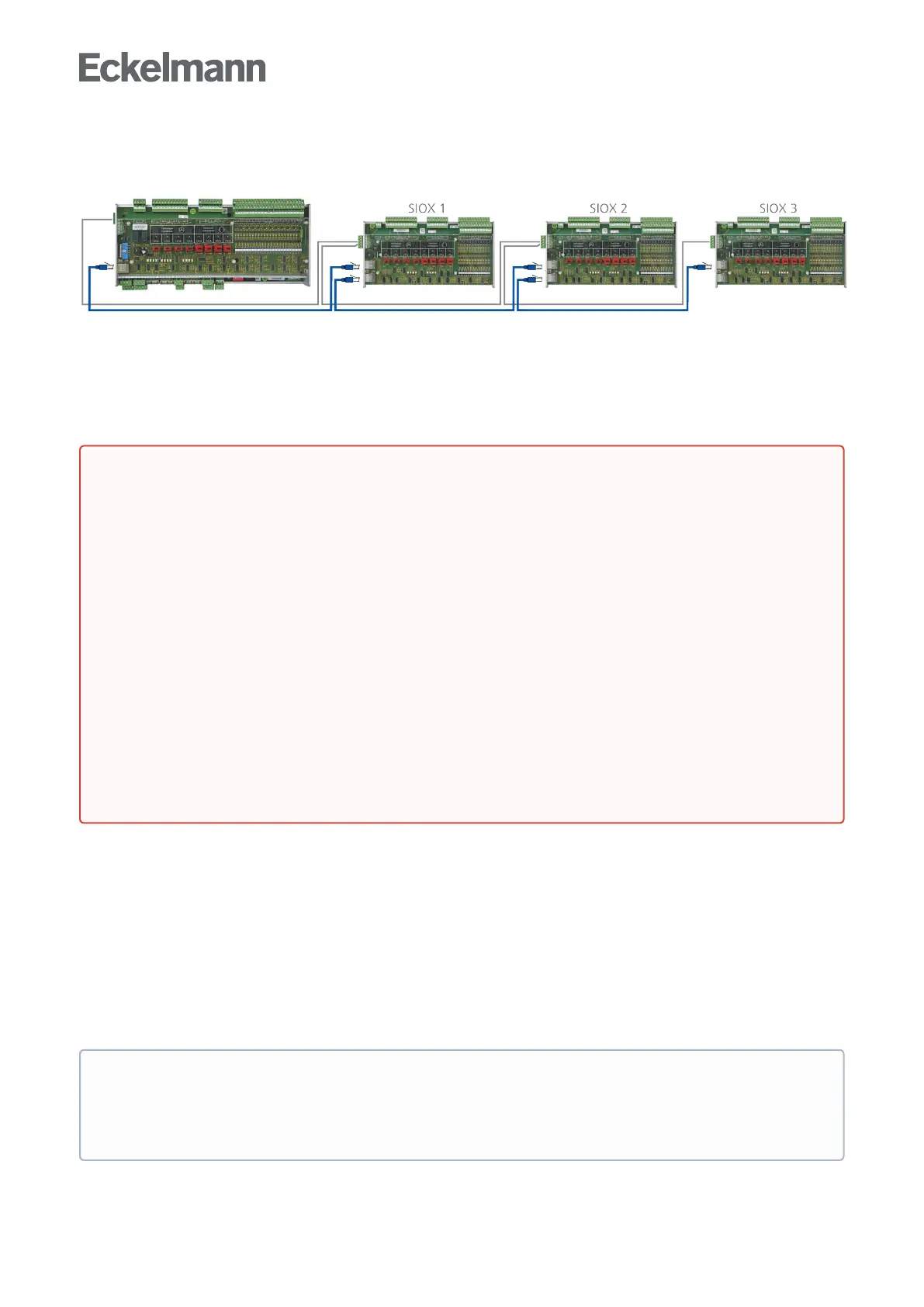
Base module GLT x010 in full expansion with max. 3 SIOX extension modules For more details, see the
chapters
Connectionsfor230VAC(top)
Connections for safety extra-low voltage (bottom)
Connections for interfaces (on the side)
10.1 Assignment of all inputs and outputs
The assignment of all digital and analogue inputs and outputs is defined by the programmer of the application
and determines which functionality each of the individual inputs and outputs has.
The hardware inputs and outputs are accessed in the software via the respective assigned address of the
process variables. In the controller, all addresses of all process variables are preset to fixed values at the
factory and cannot be changed. They can be viewed in the programming environmentCODESYS in the
controller configuration. The assignment of the permanently configured addresses in the GLT x010 hardware is
explained in more detail in the following chapters. These addresses are needed for the creation of the Signal
List which is the basis for the creation of the application.
•
•
•
•
•
DANGER
Warning about dangerous electrical voltage! Danger to life - Danger of electric shock or
malfunction! The following points must be strictly observed for the cabling:
The system must be disconnected from the power supply before detaching or inserting plug
contacts on the controller.
For analogue inputs and outputs with current or voltage interface (4..20 mA / 0..10 V), it is
essential to ensure correct polarity. Short circuits or a faulty power supply can result in
impairments of the function or even destruction of components of the controller.
All connection cables from and to the controller - with the exception of the relay outputs and the
digitalinputs–mustbeshielded. Otherwise malfunctions, e.g. faulty measurements, cannot be
ruled out.
It must also be strictly ensured that the inputs / outputs are correctly configured using the jumpers
provided for this (current or voltage interface, see chapter Configuration of the analogue inputs and
outputs).
Forthedigitalinputs,ensurethecorrectjumpersettingfor24VAC/DCor230VAC,seechapter
Configuration of the digital inputs 230 V AC and 24 V AC/DC.
ATTENTION:If230VACisappliedtoadigitalinputthathasbeenconfiguredfor24VAC,this
results in destruction of the digital inputs!
Practical tip
In order to establish a better reference to the controller configuration in CODESYS, the columns "I/O
no." which indicate the numbers of the inputs and outputs in the controller configuration are shown in
the tables of the connection assignment.