10.4.3 Assignment RS485
RS485 on the base module
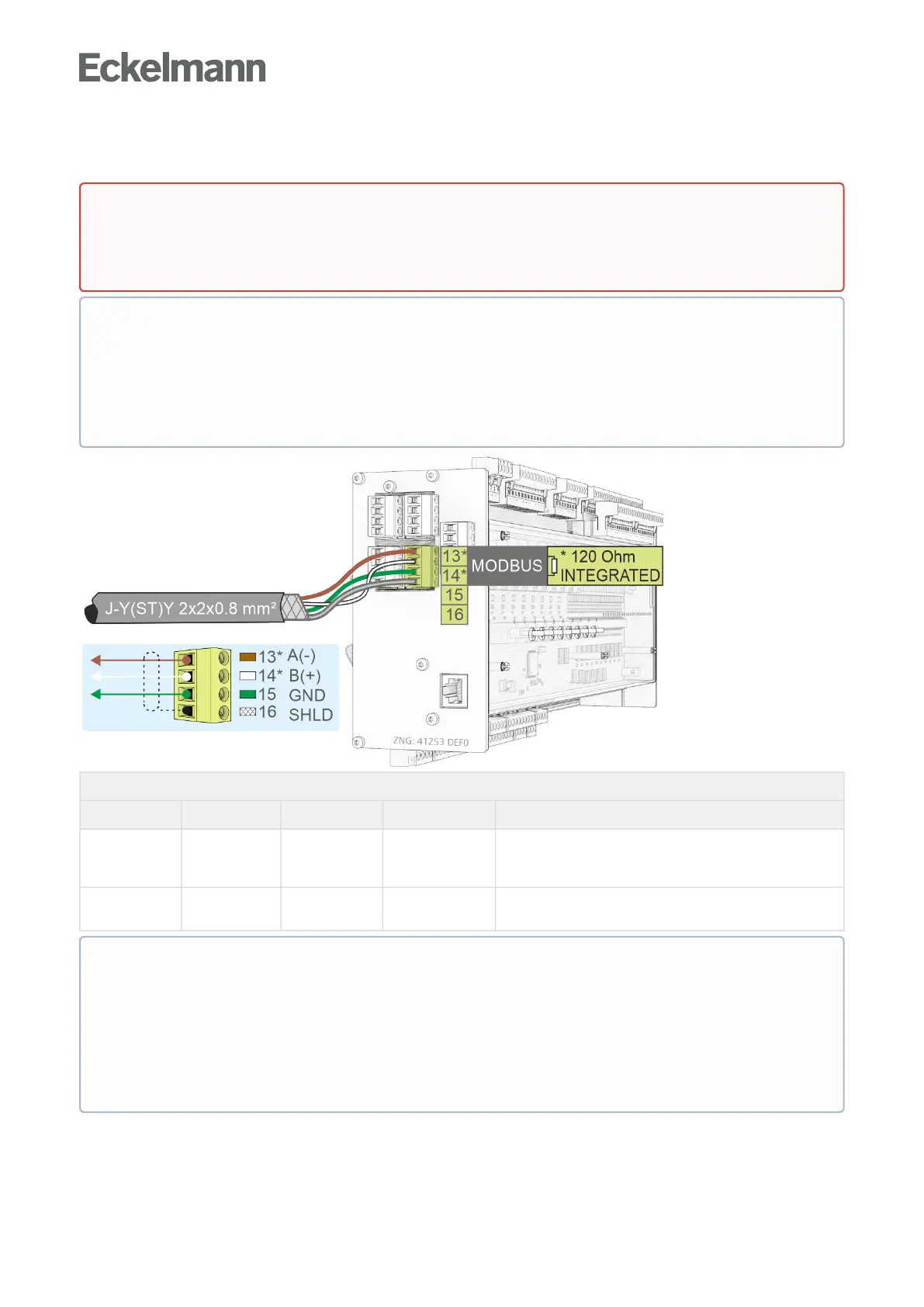
Description Terminal No. Connection Wire colour Function
RS485 13*
14*
RS485 A(-)
RS485 B(+)
brown
white
For coupling third party controllers to the Modbus,
see chapter Assignment Modbus Modules Assignment
Modbus Modules
15
16
GND
SHIELD
green
shield
Connection for RS485 and RS232 interface
Shield
For details, see chapter Setting of the interfaces TTY/RS485 using jumper J1.
DANGER
Warning about dangerous electrical voltage! Danger to life - Danger of electric shock! BEFORE
connecting and disconnecting, it must be ensured that no voltage is present at all connections of the
controller.
ATTENTION
All Modbus supply lines must be shielded (cable type J-Y(ST)Y 2x2x0.8 mm
2
), the maximum length of
the cable is 1000 m! As a general rule, care should be taken to ensure that signal cables and cables
carrying mains voltage are routed in separate cable channels
ForfurtherdetailsabouttheCANbus,seeoperatingmanual"E*LDS Basics, Safety Instructions, CAN
Bus & Modbus".
* Special feature:
A terminating resistor of 120Ohmisalreadypermanentlyinstalled (integrated) in the controller
between the terminals 13 A(-) and 14 B(+). Thus this interface represents the beginning of the
Modbus, a termination at these terminals is not required and must not be done! A terminating resistor
of 100 Ohm must only be installed at the end of the line (at the last Modbus module).
Note: From serial number "14xxxxx" onwards, a 120 Ohm terminating resistor is permanently
integrated in the controller between terminals 13/14.
The interface must be configured via jumper J1 before use.