1.
2.
3.
4.
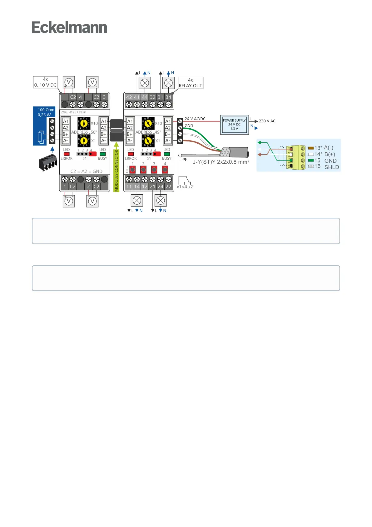
Connection of the Modbus modules to the base module and the power supply
Modbus modules can be connected via the RS485 interface on the base module to expand the I/Os.
Configuration of the Modbus modules
Setting of the Modbus address
Disconnect module from the power supply.
Set Modbus address "1..99" (address selector switches X10 and X1).
Example:
X10 = 4 = 4 x 10 = 40 and
X1 = 9 = 9 x 1 = 9
Modbus address = X10 + X1 = 40 + 9 = 49
Connect 100 Ohm terminating resistor to the last Modbus module (drawing on the left).
Supply power to module.
The communication parameters of the Modbus interface are configured in CODESYS.
* Note: Aterminatingresistorof100Ohmmust be installed at the end of the Modbus cable
(drawing on the left, part number W100R00004), for details see EDP.
The Modbus modules are set with parity = even and bit rate of 19200 bit/s at the factory. Further details
can be found in the description of the Modbus modules.