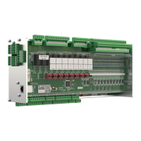
The analogue inputs (0..10 V / 4..20 mA) are configured in the "Module parameters" tab (see Controller
configuration). The selection can be found as follows:
GLT3010_V2 → Analog IO → 7 Analog Inputs
Select "Module parameters" on the right-hand side:
For orientation, a Default column is provided in which the factory setting is described. The Value column shows
the setting currently in use. The desired behaviour of the interfaces for 0..10 V or 4..20 mA is set via the drop-
down selection boxes:
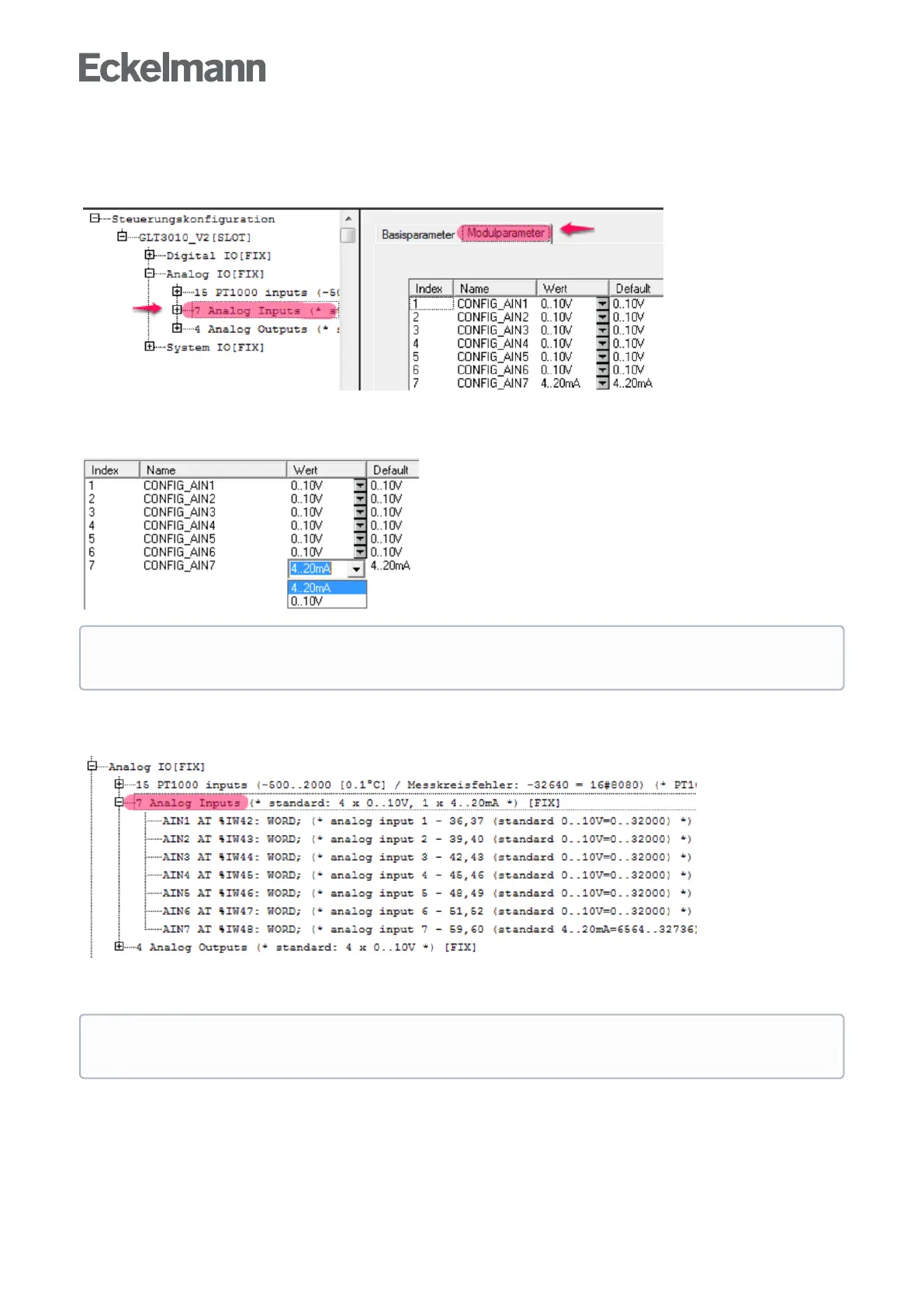
The following screenshot in the controller configuration under Controller GLT 3010_V2, in the Analogue IO
section, shows that the base module (called STANDARD) has 7 analogue inputs. Clicking on [+] opens the
following display:
Explanation: The seven analogue inputs have the IEC addresses %IW42 .. %IW48
ThepresetvariablenamesAIN1..AIN7canbeuseddirectlyinCODESYS,e.g.forIF AIN7 > 16000 then
When changing the configuration of the analogue inputs, the jumpers located on the main board must
be reconfigured.
Practical tip: For better readability of the CODESYS program, meaningful process variable names
should be defined via theSignal List and then used.