203
Technical Publication Document NO: SYSTEM-007-ENG (Ver.1.1)
HF-525Plus Installation, Operation and Service Manual
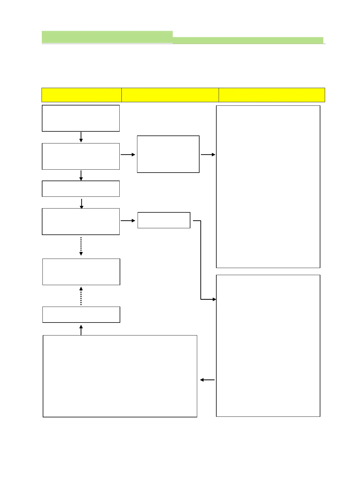
3) Check procedure
(1) Board Name: XR7-FnDBoard
(2) Functions: Controlling Tube Filament
(3) Under Tube Filament circuit trouble, check high voltage and wiring condition of circuit and then check
XR7-FnD board.
Turn on the Main power and
then turn on the Console
Power
ECO-XR5-FnD (Driver Board)
LED (D516, 517, 518)
점등상태확인
정상: LED모두 녹색점
등
LED (D516, 517, 518)
Not lighting
Normal: All LED lighted
with green
1. Check Connector (P501) and measure
the voltage on it; 230VAC is normal
2. Check Fuse (F501).
3. Fix the Relay (RL501) position and check
its functioning. Normal: Relay working.
4. Measure the voltage between Heat sink
(U406) and Test point (M5V) Normal:
5VDC ±0.1V
5. Measure the voltage between Heat sink
(U406) and KA324 (U518 pin 4); 12VDC
±0.1V is normal
6. Measure the voltage between Heat sink
(U406) and KA324 (U518 pin 11); -
12VDC ±0.1V is normal
7. In case above voltages are not good,
check input PWR of ECO-XR5-MiO
(Main Board).
8. Fix the Connector (P403) well.
1. Check HV cables. (Anode, Cathode
directions and contact condition)
2. Tube Focal LED lightening check.
3. Check cable connections between
Connector (P401) and HV Transformer.
4. Fix the RL401 Relay of focal change, and
check its functioning (Normal: Relay On -
> Large, Relay off -> Small)
5. Voltage check between Connector (P401)
pin 3 and pin 4 before Ready at Small
focus. (Normal: 35VDC ±2V)
6. Voltage check between Connector (P401)
pin 2 & 4 before Ready at Large focus.
(Normal: 35VDC ±2V)
X-ray switch could use after
Ready lamp lightening.
7. Voltage checks before Ready between Heat sink (U406) and
Resistor (R426). (Normal: approx.RMS 0.8VDC ±0.1V and voltage
is difference at each mA with Ready condition)
8. Before pressing Ready, measure the voltage between Heat sink
(U406) and KA39 3(U519 pin3) (Normal: 1VDC ±0.1V and this is
different at each mA under Ready condition)
Could use system after repair