EasyManua.ls Logo

Ecoray HF-525Plus - Fuse Capacity of Main Parts

Ecoray HF-525Plus
233 pages
Print Icon
To Next Page IconTo Next Page
To Previous Page IconTo Previous Page
Loading...
34
Technical Publication Document NO: SYSTEM-007-ENG (Ver.1.1)
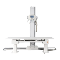
HF-525Plus Installation, Operation and Service Manual
5.6.1 Main wiring connection
Cable No
Q’ty
Cable length
(Unit: m)
Function
Remarks
Cable 1
1
Depends on
room
Three phase
power
(380VAC)
Connect line with indicated
Cable 2
1
15
Signal line
Connect generator with console
Cable 3
1
9
Power, Tube
Stator line
Connect generator with handle bar
Cable 4
1
1
Tube Stator Power
Including temperature relay signal
Cable 5
1
9
Power
Assembled with handle bar
Cable 6
1
5
Power and Signal
Assembled with Table Bucky
Cable 7
1
9
Power and Signal
Assembled with Wall Bucky
Cable 8
Variable
Depends on
room
AEC
communication
cable
Connectable Table Bucky with Wall Bucky
Cable 9
1 pair
Depends on
room
High Voltage
Cable
Connect H/V transformer with X-ray tube
Cable 10
1 pair
Depends on
room
DAP
communication
cable
Connect generator with DAP
NOTE
Refer to the wire size. Use recommended ground wire size by local regulation. And ground terminal
is located in beside of generator main fuse.
5.7 Fuse capacity of main parts. Re-Check
No
Fuse Name
Position
Capacity
Quantity
1
F1,F2
Main Fuse
500V, 63A
2
2
F3,F4
Trans Fuse
250V, 15A
2
3
F701
MiO Board
250V, 10A
1
4
F901
MiO Board
250V, 3.15A
1
5
F801
CnD Board
250V, 10A
1
6
F501
FnD Board
250V, 3.15A
1
7
F701
GC Board
250V, 20A
1
8
F700,F704,F705,F708
GC Board
250V, 5A
4
9
F702,F703,F706
GC Board
250V, 3.15A
3
10
F707
GC Board
250V, 10A
1

Table of Contents

Related product manuals