223
Technical Publication Document NO: SYSTEM-007-ENG (Ver.1.1)
HF-525Plus Installation, Operation and Service Manual
Voltage dip of
power supply line,
short-duration
interruption and
voltage variations
IEC 61000-4-11
<5 % U
T
(>95 % drop, if U
T
)
0.5 cycle
40 % U
T
(60 % drop, if U
T
)
5 cycles
70 % U
T
(30 % drop, if U
T
)
25 cycles
<5 % U
T
(>95 % drop, if U
T
)
5 seconds
Comply with all test
levels.
Prevent shut-down
and return to pre-
interference state
after manipulation
by operator.
(Power-on switch)
The quality of the main power
supply should be equivalent to that
of commercial or hospital settings.
If the HF-525 PLUS is to be
operated without a sufficient main
power supply, it is better to provide
the appropriate power using UPS or
battery.
Power frequency
(50/60 Hz)
magnetic field
IEC 61000-4-8
Power frequency magnetic field
should conform to general use or
the equivalent to that of a general
hospital environment.
NOTE: U
T
is the voltage of AC main power before the test level is applied
Electromagnetic Susceptibility
HF-525 PLUS is manufactured to be used in the electromagnetic environment designated in the below table.
The user of HF-525 PLUS should check whether the equipment is used in such an environment.
Electromagnetic Environment - Guide
Conductivity RF
IEC 61000-4-6
Radioactivity
RF
IEC 61000-4-3
3 Vrms
150 kHz to 80 MHz
3 V/m
80 MHz to 2.5 GHz
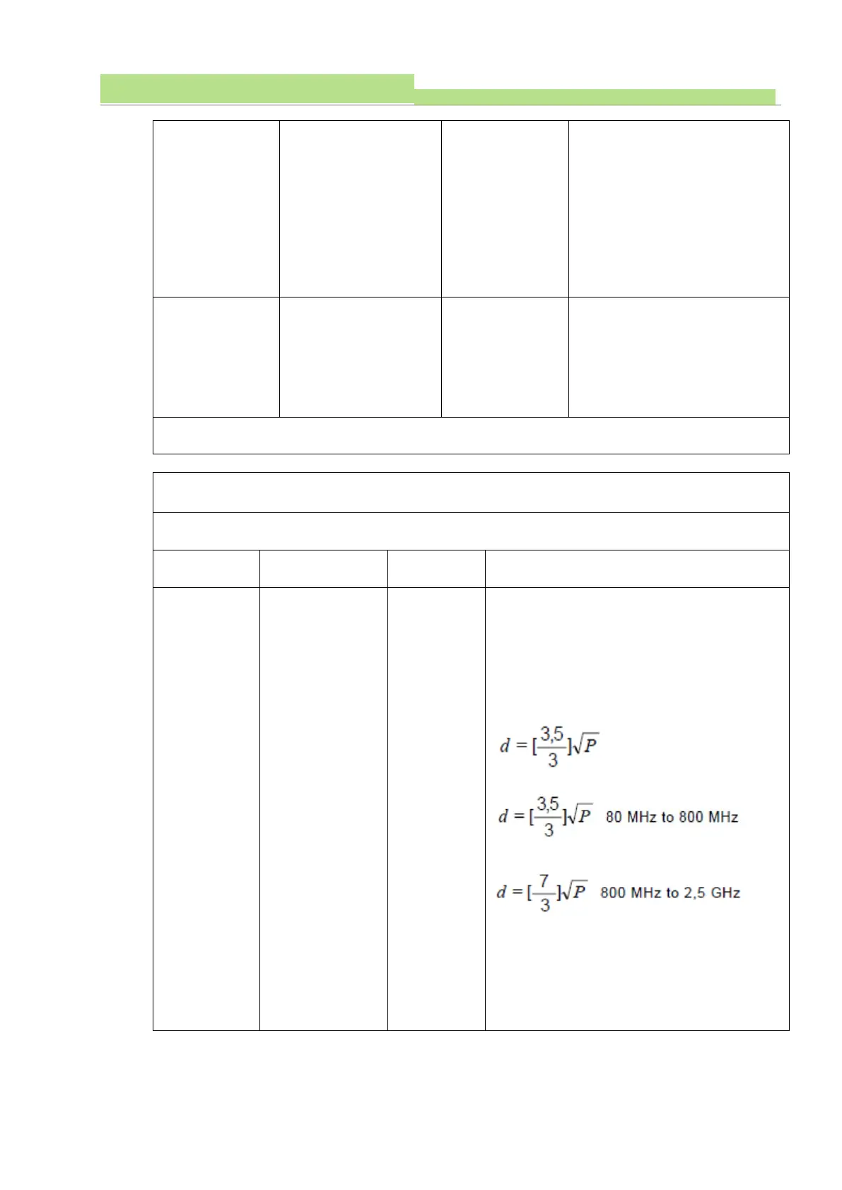
Portable and mobile RF communication equipment
must not be used from a distance closer than the
recommended separation distance, which is
determined by an equation that calculates the
distance from all parts of HF-525 PLUS (including
the cables) to the transmission frequency.
Recommended separation distance
80MHz to 800 MHz
800MHz to 2,5 GHz
P is the maximum rated output (W) of the
transmitter according to its manufacturer, and d is
the recommended separation distance (m).
The field intensity
a
from fixed RF transmitter that is
detected by measuring electromagnetic waves
should be lower than the compliance standard in
each frequency range
b
.