Document ID: OMM-00131 Rev. E
55
6.Access the adjustment nuts on the left and right side of the media fence.
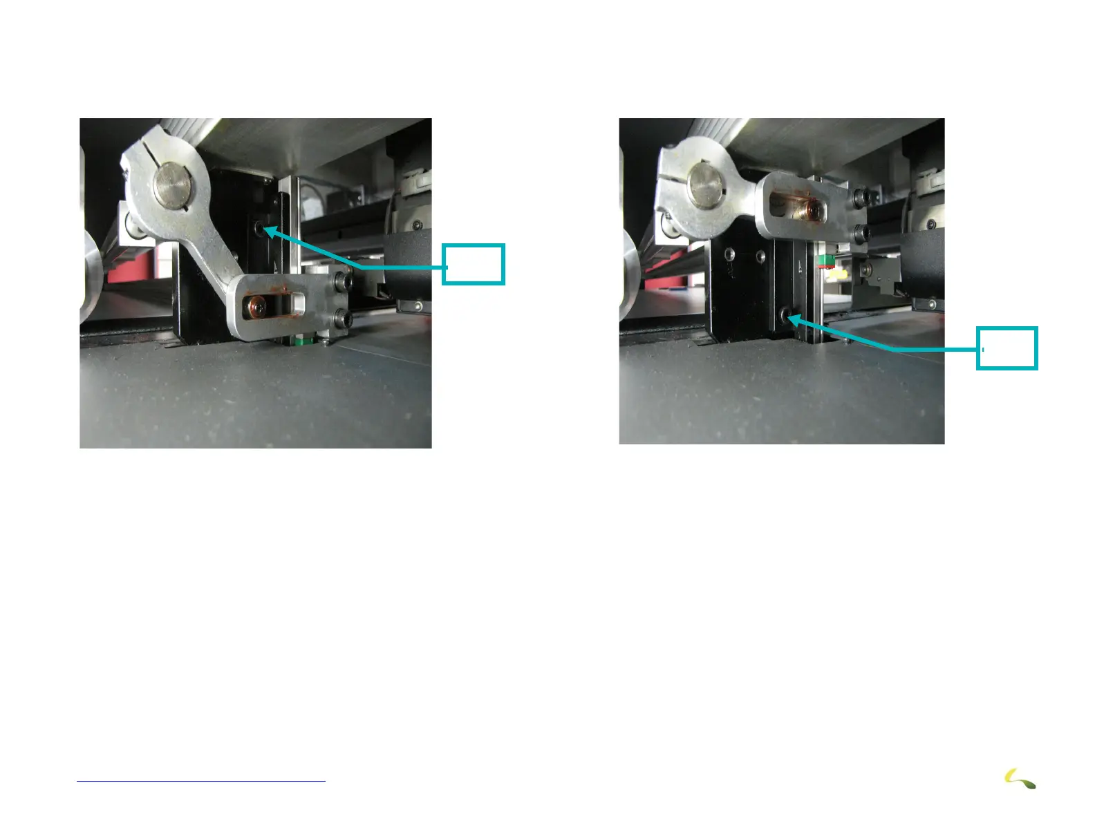
7. With the fence in the “Down” position, the upper adjustment screw and be accessed and loosened.
8. With the fence in the “Up” position, the lower adjustment screw and be accessed and loosened.
9. Do this on both sides of the fence as required.
10. With the adjustment screws loose, the fence can me moved to align with the marks and become parallel with the beam. This will
ensure that the rigid media is pulled through the printer such that it is square to the beam and will eliminate any skewing effects
to the final product.
11. Once these adjustments are completed and the fence is properly aligned with the beam, reverse the procedure to tightly secure
the adjustment screws.
Upper
Screw
Figure 3-56: Fence Adjustment Upper Screw
Lower
Screw
Figure 3-57: Fence Adjustment Lower Screw