Mounting Steps:
1. Select a suitable mounting location for the inverter.
2. Use the cardboard template to mark where the mounting
bracket bolts or screws will be installed. When installing the
bracket to studs, verify the marks for the screws are
centered over a stud.
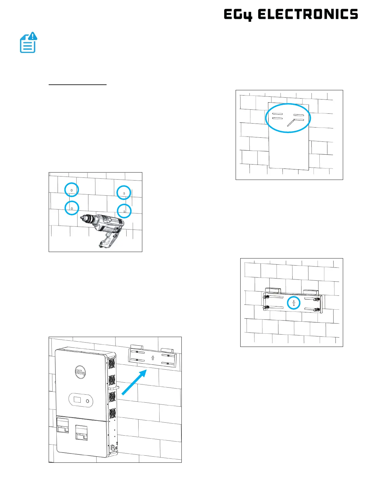
3. When installing the bracket to concrete or brick, drill 5/16
in. (8 mm) diameter holes on the marks, making sure the
holes are deeper than 2 in. (50 mm) when using the
included expansion bolts. When installing the bracket to a
stud, drill a pilot hole recommended for the screw diameter
used.
4. For concrete or brick wall installation, insert the expansion
bolts into the drilled holes. Install the bracket to the wall
ensuring the arrow is pointing up. Use the corresponding
nuts and washers (packaged together with the expansion
bolts) to affix the bracket to the wall. For stud wall
installation, insert four of the included hex head wood lag
screws into the pilot holes and affix the bracket to the wall.
5. Using the team-lift technique, place the
inverter on to the wall bracket securing it to
the wall.
NOTE:
• Ensure the surface the inverter is being mounted to can support the weight
of the unit and has proper spacing as per the diagram above.
 Loading...


