Cable Installation:
1. Before making any wiring connections, be sure to
have the inverter(s) powered off, the generator
powered off, and all circuit breakers open (off) to
prevent damage to the unit.
2. Properly identify the generator’s output lines. By
US wiring standards, L1 wire will be black, L2 will
be red, neutral will be white, and ground will be
green or bare. Once identified, remove 5/16 – 3/8
in. (8 – 10 mm) insulation from the wires.
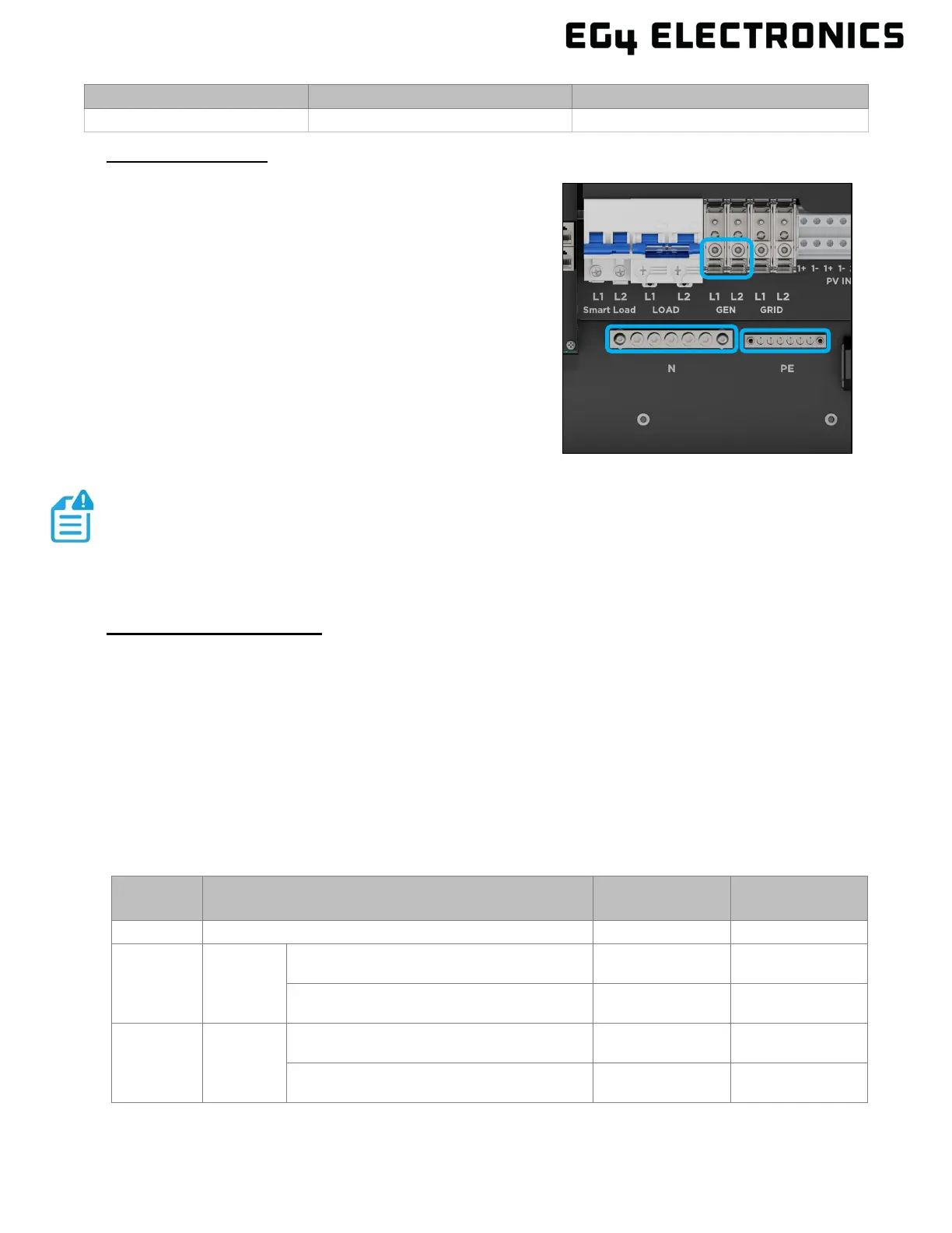
3. Ground the generator’s output ground to the
ground bus (labelled PE) in the inverter.
4. Install L1 to the GEN port’s L1 terminal, then
install L2 to the GEN port’s L2 terminal. Next,
fasten the neutral wire from the generator into the
N-BUS (Neutral Bus).
Generator Auto-Start
When properly wired and configured, the generator will start automatically when the battery voltage
is lower than the cut-off value or there is a charge request from the BMS. When the generator is
running, it will charge the batteries and excess AC power will be diverted to the AC output (LOAD) to
power loads. The pass-through relay on the inverter’s generator terminal (GEN) is 90A. When the
generator is on, ensure the total load and charge current does not exceed 90A. If the generator’s
power is not adequate to power all loads, the inverter will pull from batteries as supplemental power.
When the battery voltage exceeds the threshold for AC charging, the generator will stop.
The NO2 and COM2 ports utilize a dry contact relay to control generator auto-start (GEN 2 wire
start/stop) when the SOC or voltage reaches a set level. The GEN port (NO1, COM1) is used to
wake up the generator and then the generator can charge the battery.
TERMINAL CONNECTION
MIN. WIRE SIZE TORQUE VALUES
97 – 106 in-lbs. (11 – 12Nm)
NOTE:
When connecting multiple inverters in parallel, the generator must connect to
each inverter. Connecting to a single inverter in a multiple inverter
configuration is not supported.
UNIT
STATUS
CONDITION
DRY PORT
COM2 & NO2
GEN
NO1 & COM1
Power Off The inverter is off with no power output Open Open
Power On
Without
Grid
Battery voltage/SOC < Generator Charge
Start Voltage/SOC
Close Close
Battery voltage/SOC > Generator Charge
End Voltage/SOC
Open Open
Power On With Grid
Battery voltage/SOC < Generator Charge
Start Voltage/SOC
Close Open
Battery voltage/SOC > Generator Charge
End Voltage/SOC
Open Open