03-2009 SOI/DT-mdm FCPD-dp Quality-fz 44/91 599 70 56-70
YES
NO
YES
NO
NO
YES
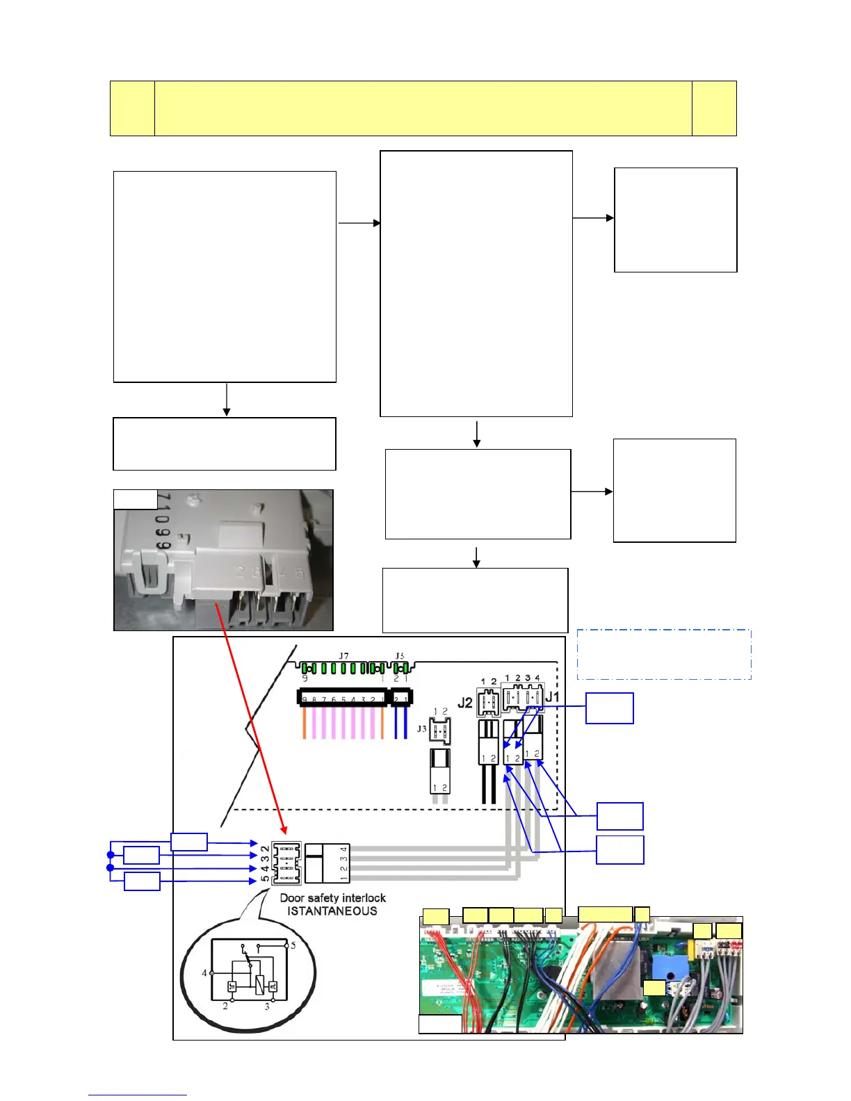
Tests to be performed:
E43
E43: Problems with the component (triac) which actions the door
interlock
(4-contact device)
E43
Replace the door
interlock and
restart the
diagnostic cycle
to check for
further alarms.
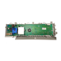
Replace the circuit board and restart
the diagnostic cycle to check for
further alarms.
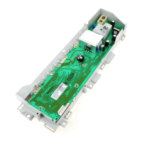
If there are traces of burning
on the circuit board, refer to
page 90
fig. 28
n Ω
∞
n Ω
n Ω
∞ Ω
n Ω
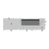
To check the wiring, (with the door
open), measure the following
wiring connectors (fig.4):
- between J1-1 and J1-3, the
circuit must NOT be open
(measure the resistive value of the
PTC).
- between J1-1 and J1-4 the circuit
must NOT be open (measure the
resistive value of the PTC).
- between J1-1 and J1-2, the
circuit must be OPEN.
Is the system OK?
Measure the continuity across
connector J1 (PCB) and the
door interlock connector.
Is the wriring OK?
Replace the
wiring and restart
the diagnostic
cycle to check for
further alarms.
Replace the circuit board and
restart the diagnostic cycle to
check for further alarms.
Circuit
board
J1
J2
U3
J5
J7
J8J9
J10J11
J16
Fig.4
Detach the connectors of the
door interlock and measure
on the component (fig. 28):
- across connectors 3 and 4
the circuit must NOT be open
(Measure the resistive value
of the PTC).
- across connectors 2 and 4
the circuit must NOT be open
(Measure the resistive value
of the PTC).
- across connectors 4 and 5
the circuit must be OPEN
(the numbers are printed on
the component).
Is the door safety interlock
OK?