03-2009 SOI/DT-mdm FCPD-dp Quality-fz 47/91 599 70 56-70
YES
YES
NO
YES
YES
NO
NO
YES
NO
NO
YES
YES
NO
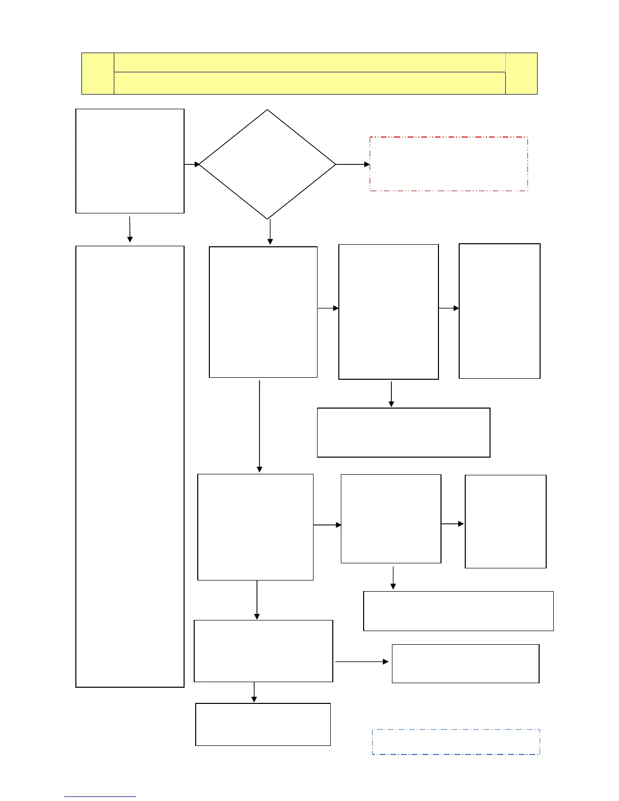
E52: No signal from the motor tachometric generator (first part)
E52
Cycle blocked after 5 attempts during the cycle or immediately if detected at the start or during
diagnostics.
E52
Tests to be performed:
Perform phase 7
of the diagnostic cycle
(the drum rotates at
55 rpm clockwise 55
rpm anti-clockwise
with pulse at 250
rpm). Does the motor
rotate correctly?
The motor protection
circuit-breaker has
probably tripped.
Before replacing the
motor, check the
following
→ that the hydraulic
circuit of the pressure
switch is OK (minor
leaks from the tube
may cause greater
than normal water
fills, and the motor
may overheat)
→ that the bearings
are OK and the drum
rotates without friction
→ that the mains
voltage is correct (if
the voltage is too low,
though not lower than
the EH3 alarm
threshold, the motor
might not start)
Restart the diagnostic
cycle to check for
further alarms.
Check/replace the wiring and restart
the diagnostic cycle to check for
further alarms.
Replace the
motor or the
tachometric
generator and
restart the
diagnostic cycle
to check for
further alarms.
Measure across the
same terminals of the
wiring connector
(J7-7 and J7-8) and the
structure of the
appliance.
Is there any current
leakage?
- see fig 6?
Check for the
positioning of the
tachometric
generator.
Is it correct?
- see fig.12) -
Replace the main circuit board and
restart the diagnostic cycle to check for
further alarms.
Replace the
motor/
tachometric
generator and
restart the
diagnostic cycle
to check for
further alarms.
Check/replace the wiring and
restart the diagnostic cycle to
check for further alarms.
Does the
motor rotate
for a few
moments and
then sto
?
The motor does not rotate at
all.
- see page 49-
NO
Measure across the
terminals of the wiring
connector
J7-7 and J7-8.
Are the values (Ω) of
the tachometric
generator correct?
(refer to page 50
- Step 4, phase “A” ).
Detach the
connector from the
motor and measure
(Ω) the coil of the
tachometric
generator
-see fig.11-
Is the value
correct?
(refer to page 50
Step 4 - phase “A”).
If there are traces of burning on the
circuit board, refer to page 90
Replace the motor and
restart the diagnostic cycle
to check for further alarms.
Detach the connector from
motor and measure across
terminals and motor shield. –
(see fig.10)-
Is there an