11
9500
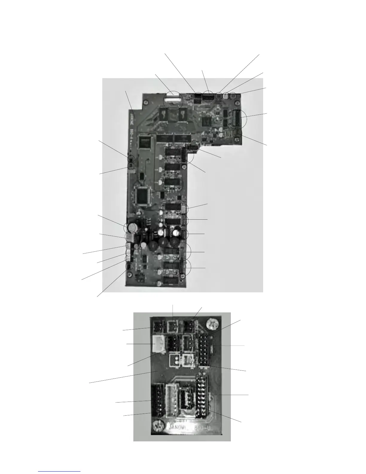
Connector Connection Diagaram
Please see the following connector connection diagram for the printed circuit board
A and U.
Printed circuit board R (White)
Bobbin winder (Black)
Printed circuit board U
(Black)
Printed circuit board L2 (Gray)
Printed circuit board L2 (White)
Printed circuit board F1 (Red)
Printed circuit board F2 (Black)
Slide volume (Red)
Printed circuit board B (Black)
Printed circuit board U (Black)
LCD Motor (Top/Bottom)
Printed circuit board P (Black)
Printed circuit board Q (Black)
Feed motor (Red)
Printed circuit board S1 (Black)
Presser foot lifter sensor (Brown)
P foot sensor (Blue)
Printed circuit board A (Black)
Printed circuit board L3 (Gray)
Printed circuit board A (Black)
Needle threader motor (Black)
Printed circuit board A
LCD detection switch
(Top position)(Blue)
LCD detection switch
(Bottom position)(Brown)
Switching regulator (White)
DC Motor (White)
Remaining bobbin thread
solenoid (Black)
Thread cutter solenoid
(White)
Upper shaft disconnect
solenoid (Red)
Potention meter (Blue)
Needle threader motor detection
switch (Bottom)(Brown)
Needle threader motor
detection switch (Top)(Blue)
Buttonhole sensor (White)
Thread cutter sensor (Black)
Printed circuit board U
Zigzag width motor (Black)
Ttread tension motor (Gray)



 To Next Page