13
9500
(A)
(B)
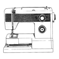
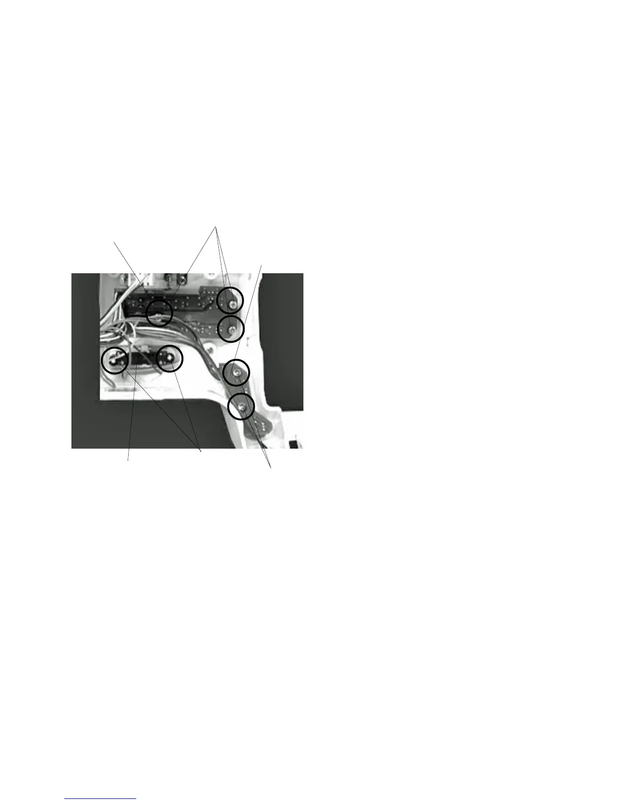
Replacing Printed Circuit Board F1, F2/Slide Volume
Printed circuit board F1
To remove:
1 Remove the front cover.
2 Pull out the connector from the printed circuit
board A.
3 Remove Screws (A) (2 pieces) and remove
the Printed circuit board F 1 .
To attach:
4Follow the above procedure in reverse.
Printed circuit board F2
To remove:
1 Remove the front cover.
2 Pull out the connector from the printed circuit
board A.
3 Remove Screws (B) (3 pieces) and remove
the Printed circuit board F 2 .
To attach:
4Follow the above procedure in reverse.
Slide volume
To remove:
1 Remove the front cover.
2 Pull out the Slide volume connector from the
printed circuit board A.
3 Remove the CS ring (2 pieces) and remove
the slide volume .
To attach:
4Follow the above procedure in reverse.
q
q
w
w
e
e
r
r
 Loading...