41
9500
(C)
(C)
(C)
(C)
(C)
16.5 mm
3.6 mm
(A)
(B)
(Y)
(X)
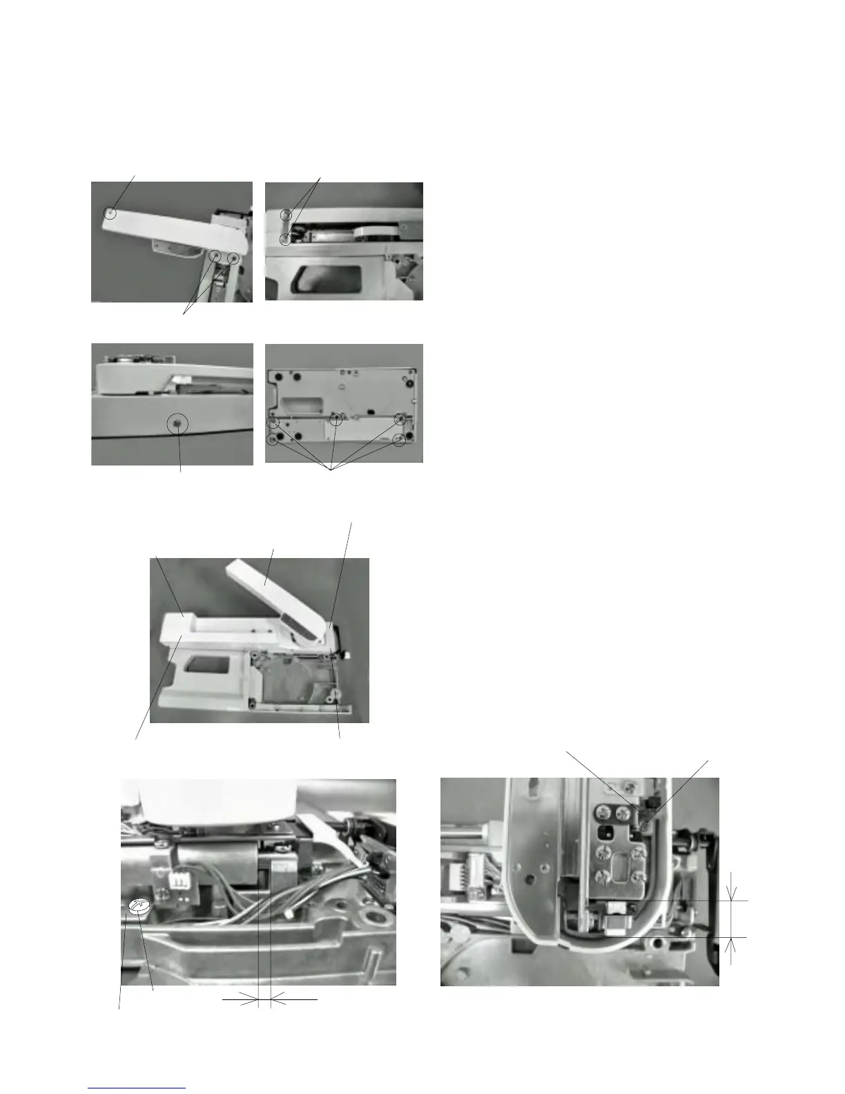
Adjusting X and Y Sensors
1Turn the power switch “ON”. (Initial setting)
2Turn the power switch “OFF” and remove the base
unit.
3 Remove the Y carriage cover
qq
qq
q, X carriage cover
ww
ww
w, X carriage cap
ee
ee
e and embroidery base cover
rr
rr
r and
tt
tt
t.
4 Loosen screw (A) to adjust dimension (Y) to
16.5 mm by moving the Y sensor attaching plate .
5 Loosen screw (B) to adjust dimension (X) to 3.6 mm
by moving the X sensor attaching plate .
7 Attach the Y carriage cover , X carriage cover ,
X carriage cap and embroidery base cover 1
and 2 .
8 Attach the base.
y
u
q
w
e
r
t
q
w
e
r
t
y
u