44
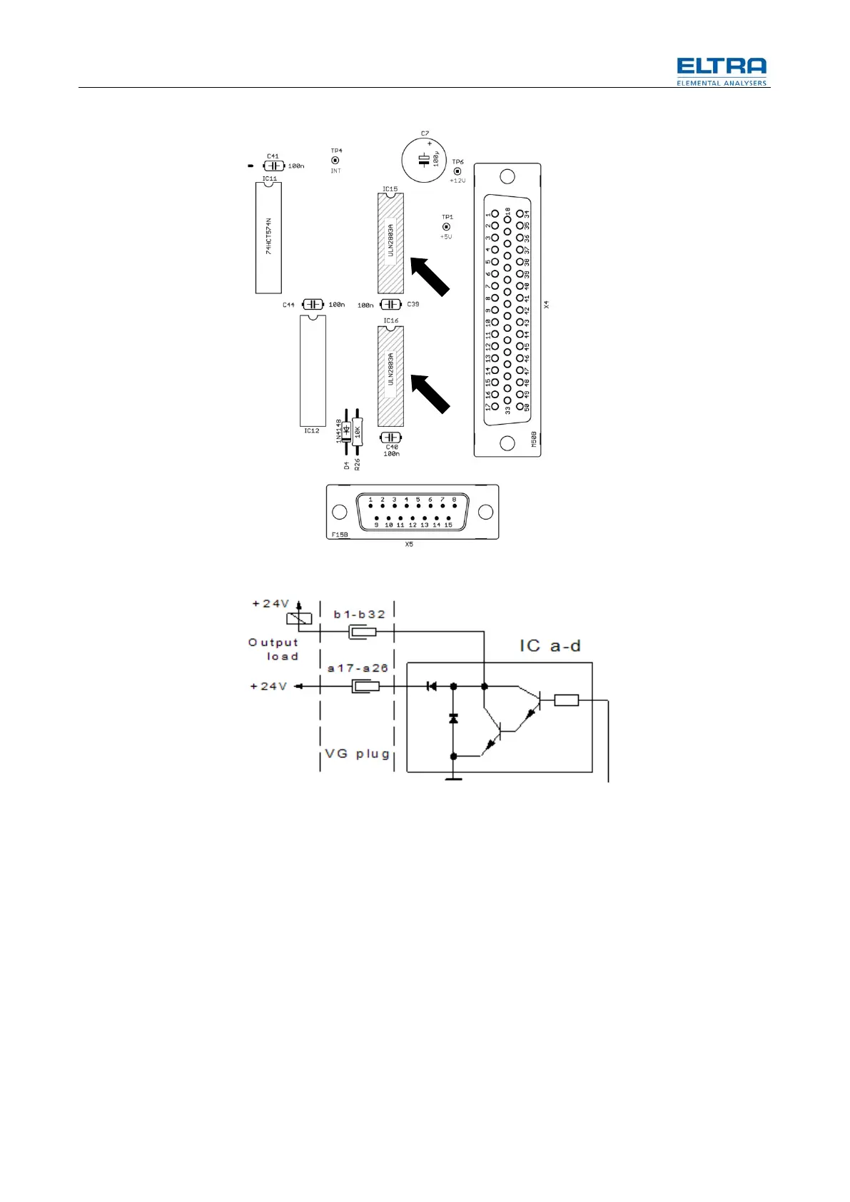
Fig. 22: Partial image of the mother microcontroller board
Fig. 19: Circuit diagram
These IC’s act as a power switch in order to energize solenoid valves inside the
analyzer or to send control signals.
These drivers are designed for continuous current of 500mA each output, so that
the 200mA taken by the valves are far below their specified current.
Therefore they are very reliable. In fact they never fail with 200mA load. We only
have reports of failure when somebody tries to measure the valve voltages,
accidentally causing a short circuit.
In case of short circuit, the drivers are immediately destroyed.
Therefore it is practically not possible to realize the short circuit. It is however not a
coincident when drivers working for lots of years in an analyzer, fail just in the
moment when somebody tries to measure the voltages of the valves. Therefore we
strongly suggest to only measure the valve voltages after all other instructions of
this manual are carefully followed, but without solving the problems.