24 1019567 REV. 03
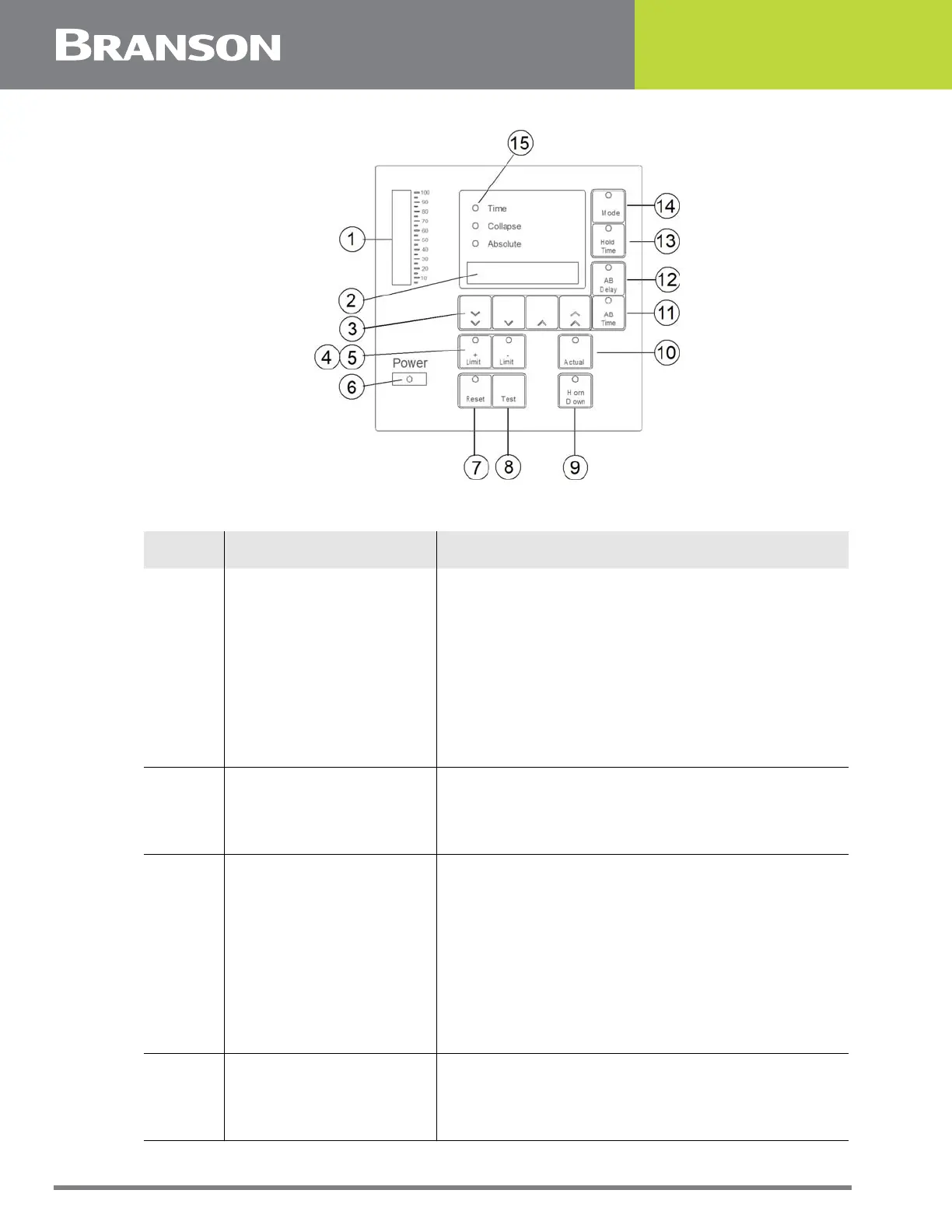
Figure 2.4 Front Panel Displays, IW+
Table 2.3 Front Panel Displays IW+
Item Name Function
1 Power Bargraph
This 20 segment bargraph displays the power
level during the Test mode; or the power applied
to the workpiece during a weld cycle. While in
READY state, the graph displays the peak power
of the last weld cycle. These readings can be
expanded by altering DIP switch settings. When
using the 2x scale, the uppermost segment will
blink. Refer to Section 4.11.1 ’Setting DIP
Switches’, of your Operating Manual for further
information about DIP settings.
2 Numeric Display
During a weld cycle, indicates the current weld
state code, if enabled, or the currently selected
parameter’s value. At the end of the weld cycle, it
displays alarms.
3 Up/Down Switches
Once you have selected weld parameters to
change, these four switches increase or decrease
your selected parameters displayed in the
NUMERIC DISPLAY. From left to right, these
switches a re referred to as the FAST DOWN
switch, the SLOW DOWN switch, the SLOW UP
switch, and the FAST UP switch. Pressing these
switches will have no effect until you have
selected parameters to change. These switches
will be disabled when Display Lock is active.
4 + Limit Switch
A 2000IW+ only feature - selects the maximum
value for the mode you are in. When pressed, the
switch LED will light. This switch is only active
after you have pressed MODE.