116 1019567 REV. 03
Unplug the encoder connector from the Controller Board. (When unplugging, hold the plug
- not the cable.)
Hold the encoder in place; then remove the four retaining screws and washers (Figure
5.33 Removing the Linear Optical Encoder (IW+ Only)).
5.5.17 Replacing the Linear Optical Encoder
To install the replacements encoder you need the following:
• Loctite
®
222 (or equivalent); apply one or two drops to all four retaining screws.
• An accurate torque wrench
1. Mount the replacement encoder onto the carriage:
• install the two long screws through the Body section (
Figure 5.33 Removing the Linear Optical
Encoder (IW+ Only)); and tighten the screws a few turns
2. Insert the top retaining screw and washer; tighten the screw a few turns
3. Hold the encoder against the mounting bracket (
Figure 5.33 Removing the Linear Optical Encoder
(IW+ Only)) and insert the retaining screw and washer. Tighten the screw a few turns
4. Use a torque wrench to tighten all four retaining screws to a force of 18 in-lbs. Do not overtighten
the screws
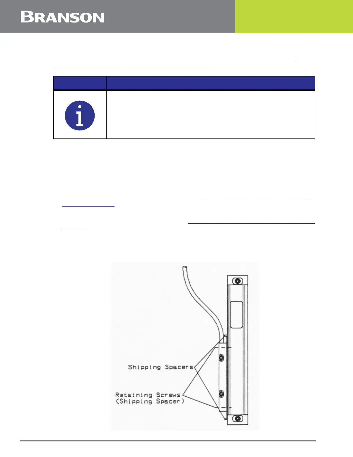
Figure 5.34 Shipping Spacers
NOTICE
Keep track of the retaining screws: short screws for the Read section;
long screws for the Body section.