1019567 REV. 03 41
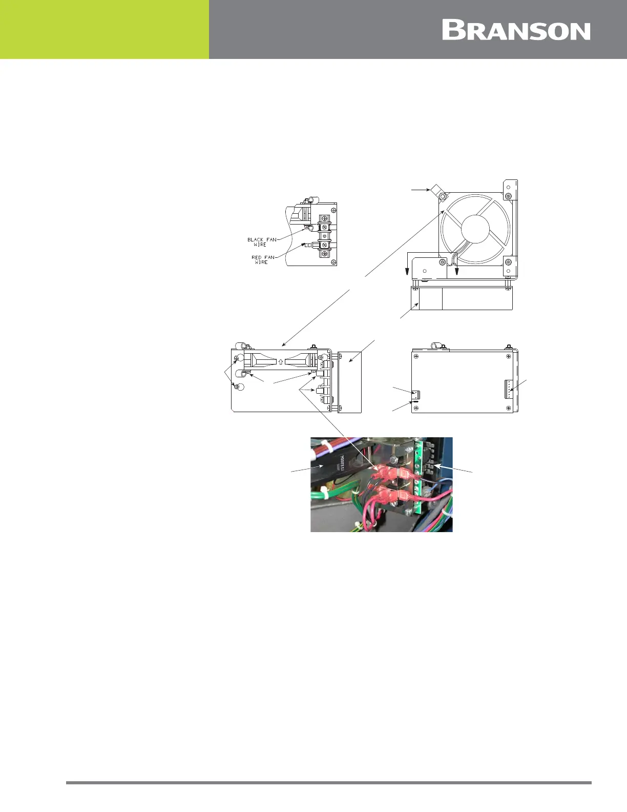
DC Power Module
The Switching DC Power Module rectifies, filters, and regulates the AC voltages from the
Line Transformer into DC voltages for the System Control Module.
Figure 3.5 DC Power Module
3.3.2 User I/O
The Alarm Connector provides status outputs and an EXTERNAL RESET switch connection
to customer supplied controls. Connection is via a J971 cable from the 25 pin connector on
the welder’s rear panel. The cable is available in 8 ft./2.5 m, 15 ft./4.5 m, or 25 ft./7.5 m
lengths.
The EXTERNAL RESET switch operates in exactly the same manner as the front panel
RESET switch, Applying +24V DC to the EXTERNAL RESET input (pin 25) for a minimum of
20 ms will reset the welder.
The status outputs available from the interface are SOLENOID OUTPUT (pin 13), GENERAL
ALARM (pin 18), READY (signal - pin 19, relay - pins 9 and 10), and WELD ON (pin 20).
The SOLENOID OUTPUT provides a negative logic output when referenced to the +24V DC
source (pins 5 and 6). GENERAL ALARM, READY AND WELD ON signals provide a negative
logic output when reference to 24V RTN (pins 21, 22, and 23).
FAN POWER
SUPPLY
FRONT VIEW TOP VIEW
END VIEW
2
4 (4 PLACES)
6
1
GND
5
FAN
POWER
SUPPLY
A
A
VIEW A - A
3 PWR INPUT