G3 Series EtherCAT
TM
Technical Manual
10-100
Subject to change without notice
www.asco.com/g3
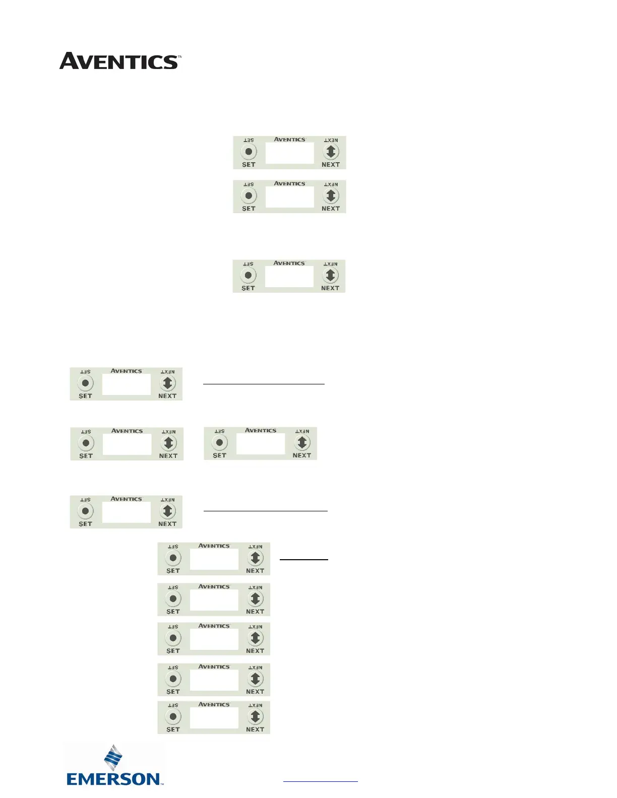
Analog Module / I/O Mapping
Displays the starting Input and Output byte address for the module
Analog Module / Module Number
Displays the module number; identifying its position in the G3 I/O system.
Analog Module / Alarm Settings
Allows the setting of low and high alarms for analog inputs and outputs
1. Press the SET button to enter the Alarm Settings sub-
menu.
2. Press the SET button to Disable all alarms (default
setting)
*Note- Setting the Minimum value for Low alarm and
the Maximum value for High alarm (for a channel)
disables the alarm for that channel.
3. Press the NEXT button to scroll to the appropriate
analog channel.
4. Press the SET button to set the LO alarm setting
a. Push the SET button to access the menu and
enter the alarm value
5. Press the NEXT button to set the HI alarm setting.
a. Push the SET button to access the menu and
enter the alarm value
b. Accept the changes by selecting Y and
pushing SET
6. Press the SET button while in the RETURN screen to
return to the main menu
I/O MAPPING
INPUT BYTE XX
I/O MAPPING
OUTPUT BYTE XX
MODULE NUMBER
XX
ALARM SETTINGS
SET ALARM
DISABLE ALARMS
DISABLING
ALARMS
SET ALARM
CHANNEL AXX
SET ALARM
LO=X.XX
SET ALARM
HI=X.XX
SET ALARM
LO=X.XX
ACCEPT
X.XX Y N
SET ALARM A0
RETURN
 Loading...


