G3 Series EtherCAT
TM
Technical Manual
5-48
Subject to change without notice
www.asco.com/g3
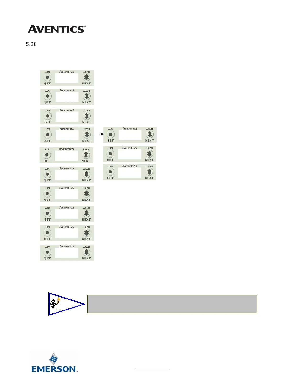
Diagnostics
• The UNSW POWER screen indicates the voltage level present
on the UNSW (Node & Input) power pins (Pin No. 2 and 3) of
the main power connector.
1. All diagnostic information is read only
2. Press the SET button to enter DIAGNOSTICS sub-
menu.
3. Press the NEXT button to scroll through the main
diagnostic menu choices.
a. SET SELF TEST
i. - Please see following page for
description
b. USNW POWER
i. - Displays voltage level of unswitched
power (Node & Inputs)
c. NETWORK DATA
i. - Displays the network diagnostics
d. FIRMWARE REVISION
i. - For service personnel
e. FIRMWARE BUILD
i. - For service personnel
f. LOAD FIRMWARE
i. - For service personnel
g. BOOTCODE REVISION
i. - For service personnel
h. BOOTCODE BUILD
i. - For service personnel
i. PART NUMBER
i. - Displays replacement part number of
module
j. RETURN TO MAIN MENU
DIAGNOSTICS
TEST
24.83 V
ERRORS
FULL
100 MBPS
1.1
BUILD
FIRMWARE
XXXXX
240-181
MAIN MENU
 Loading...


