G3 Series EtherCAT
TM
Technical Manual
13-145
Subject to change without notice
www.asco.com/g3
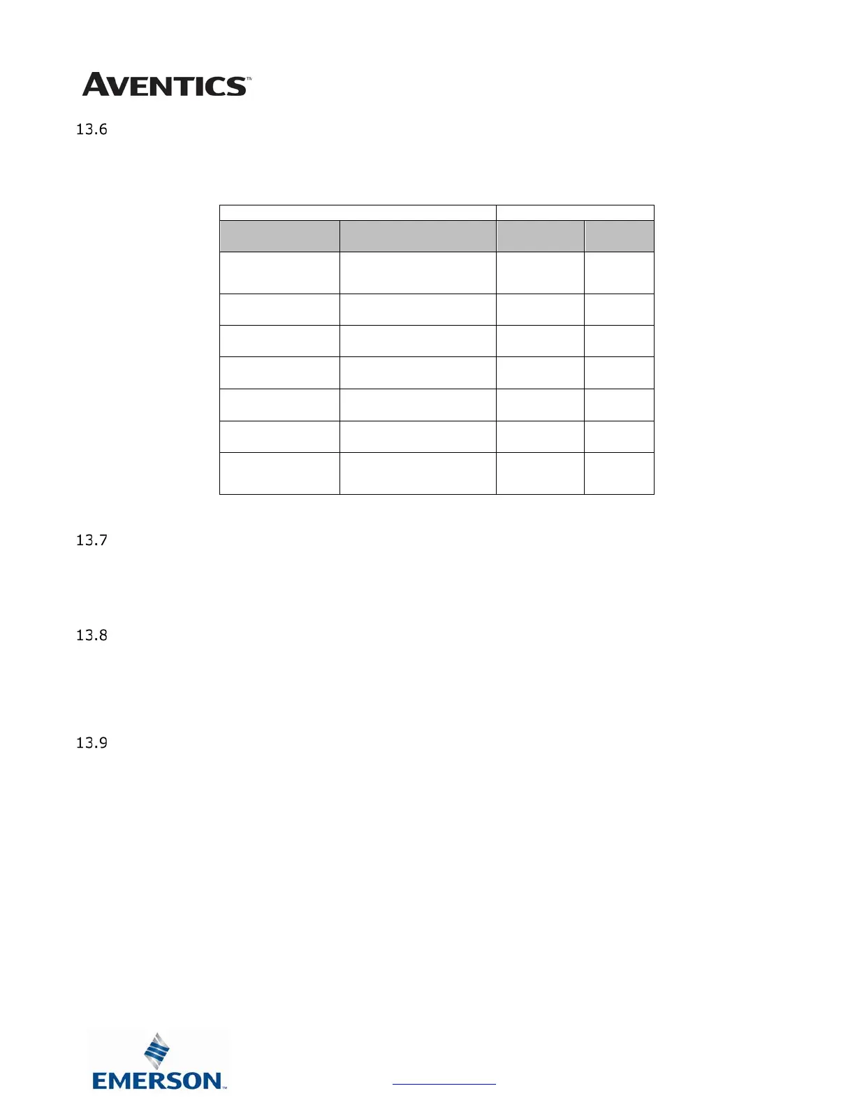
User Configurable Device Parameters
The Aventics’ G3 EtherCAT
TM
node allows the user to set many user options which define how the manifold behaves in
certain instances. The following is a description of these device parameters.
Name Description Display
Web
Server
IP Address
access the node web
X X
Gateway IP
Set the Gateway
IP address
X X
Params Lock
Selects Parameters
Locked/Unlocked
√ √
Config Lock
Selects I/O Configuration
Locked/Unlocked
√ √
Diagnostic Word
Enables / Disables the
√ X
I/O Diagnostic
Status
Allocates I/O diagnostic
status bits
√ X
Output Fault
Action
use idle value attribute
√ X
Parameters Lock
This parameter lock is used to lock out changes to all node configuration parameters (except parameter lock). Once
the manifold is commissioned the Parameters lock should be set to “LOCKED” to ensure that parameters are not
unintentionally modified.
I/O Configuration Lock
This I/O configuration lock parameter is used to lock the I/O configuration of the manifold. The manifold’s I/O
configuration map is determined on power-up of the node. Once the manifold is commissioned the I/O configuration
lock should be set to “LOCKED” to ensure the I/O will not re-map in the event of an I/O module failure. If an I/O
module fails with configuration locked the node will report an I/O module missing at the location of the failed module.
Communication Fault Mode Parameter
This parameter is used to describe characteristics or behaviors of output points (bits). The parameter shown below is
used to determine what state the outputs will have, during a “Fault” event. The Communication Fault Mode parameter
will allow control of all output points on the manifold.
The user, through PLC configuration settings, can determine how the outputs behave when a communication fault
action occurs. These settings are non-volatile and thus will not change upon loss of power.
The two behavior options are:
1. Turn Off All Outputs
2. Maintain Last Output State
 Loading...


