G3 Series EtherCAT
TM
Technical Manual
1-4
Subject to change without notice
www.asco.com/g3
Table of Contents
About EtherCAT ............................................................................................................................ 1-6
Overview .............................................................................................................................. 1-6
G3 EtherCAT
TM
Features ......................................................................................................... 1-6
G3 Introduction ............................................................................................................................ 2-7
G3 Electronics Modularity........................................................................................................ 2-8
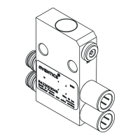
500 Series Pneumatic Valve Manifold ....................................................................................... 2-9
500 Series Manifold Stations ................................................................................................. 2-10
500 Series Z-Board™ Connectors........................................................................................... 2-11
2000 Series Pneumatic Valve Manifold .................................................................................... 2-12
2000 Series Z-Board™ Connectors ......................................................................................... 2-13
2000 Series Z-Board™ and Ribbon Cable Example ................................................................... 2-14
2000 Series Z-Board™ with Valve Side Sub-D Example ............................................................ 2-15
Zoned Power .............................................................................................................................. 3-16
503 Series Zoned Power application ....................................................................................... 3-16
503 Series Zoned Power example .......................................................................................... 3-17
Communication Module ................................................................................................................ 4-18
EtherCAT
TM
Communication Module (Node) ............................................................................. 4-18
Communication Module Description ........................................................................................ 4-19
Connector Pin-Outs .............................................................................................................. 4-20
Electrical Connections........................................................................................................... 4-21
Ethernet Straight-Through Cabling Diagrams .......................................................................... 4-23
Ground Wiring ..................................................................................................................... 4-24
Power Consumption ............................................................................................................. 4-25
Recommended External Fuses ............................................................................................... 4-26
Diagnostics ......................................................................................................................... 4-27
Output Short Circuit Protection .............................................................................................. 4-28
G3 Graphic Display ...................................................................................................................... 5-29
Main Menu Structure ............................................................................................................ 5-30
EtherCAT
TM
Operating States (Default Display) ........................................................................ 5-31
Station Alias Sub-Menu ........................................................................................................ 5-32
IP Address .......................................................................................................................... 5-33
Subnet Mask ....................................................................................................................... 5-33
Gateway IP ......................................................................................................................... 5-34
Config Mode ........................................................................................................................ 5-35
Web-Server ........................................................................................................................ 5-36
EtherCAT
TM
communication ................................................................................................... 5-37
MAC Address ....................................................................................................................... 5-38
Advanced Settings - I/O Diag. Menu ...................................................................................... 5-39
Advanced Settings - Diagnostic Word ..................................................................................... 5-40
Advanced Settings – Comm. Fault ......................................................................................... 5-41
Advanced Settings – Brightness ............................................................................................. 5-42
Advanced Settings – Flip Display ........................................................................................... 5-43
Advanced Settings – Parameters Lock .................................................................................... 5-44
Advanced Settings – Configuration Lock ................................................................................. 5-45
Factory Defaults .................................................................................................................. 5-46
Diagnostics - Self Test Mode ................................................................................................. 5-47
Diagnostics ......................................................................................................................... 5-48
Network and Sub-Network Error Codes ................................................................................... 5-49
Error Messages .................................................................................................................... 5-50
ARM – Auto Recovery Module (Optional) ........................................................................................ 6-51
ARM process flowchart ......................................................................................................... 6-52
Distribution ................................................................................................................................ 7-53
Sub-Bus Distribution Modules ................................................................................................ 7-54
580 Series Sub-Bus Valve Module .......................................................................................... 7-58
Sub-Bus Hub Module ............................................................................................................ 7-59
Sub-Bus Cables ................................................................................................................... 7-60
 Loading...