G3 Series EtherCAT
TM
Technical Manual
11-105
Subject to change without notice
www.asco.com/g3
Sensor Wiring Diagrams
24 VDC Module Supply (Via G3 System Aux. Power Connection)
RTD (Resistive Temperature Detector),
4 per Module
Pt100, Pt200, Pt500, Pt1000, Ni100, Ni1000
Supported Temperature Coefficients
Signed Integer; Two’s complement.
Field Calibration w/ high tolerance (± 0.005%) 100 ohm and 350
Input Update (filter) Rate
Adjustable (5-20mS), factory default: 5mS
0.1% of full scale @ 25° C
M12 4 Pin Female (Accepts 5 Pin)
-10º to 115º F (-23º to 46º C)
95% relative humidity: non-condensing
IP65 (with appropriate assembly and terminations)
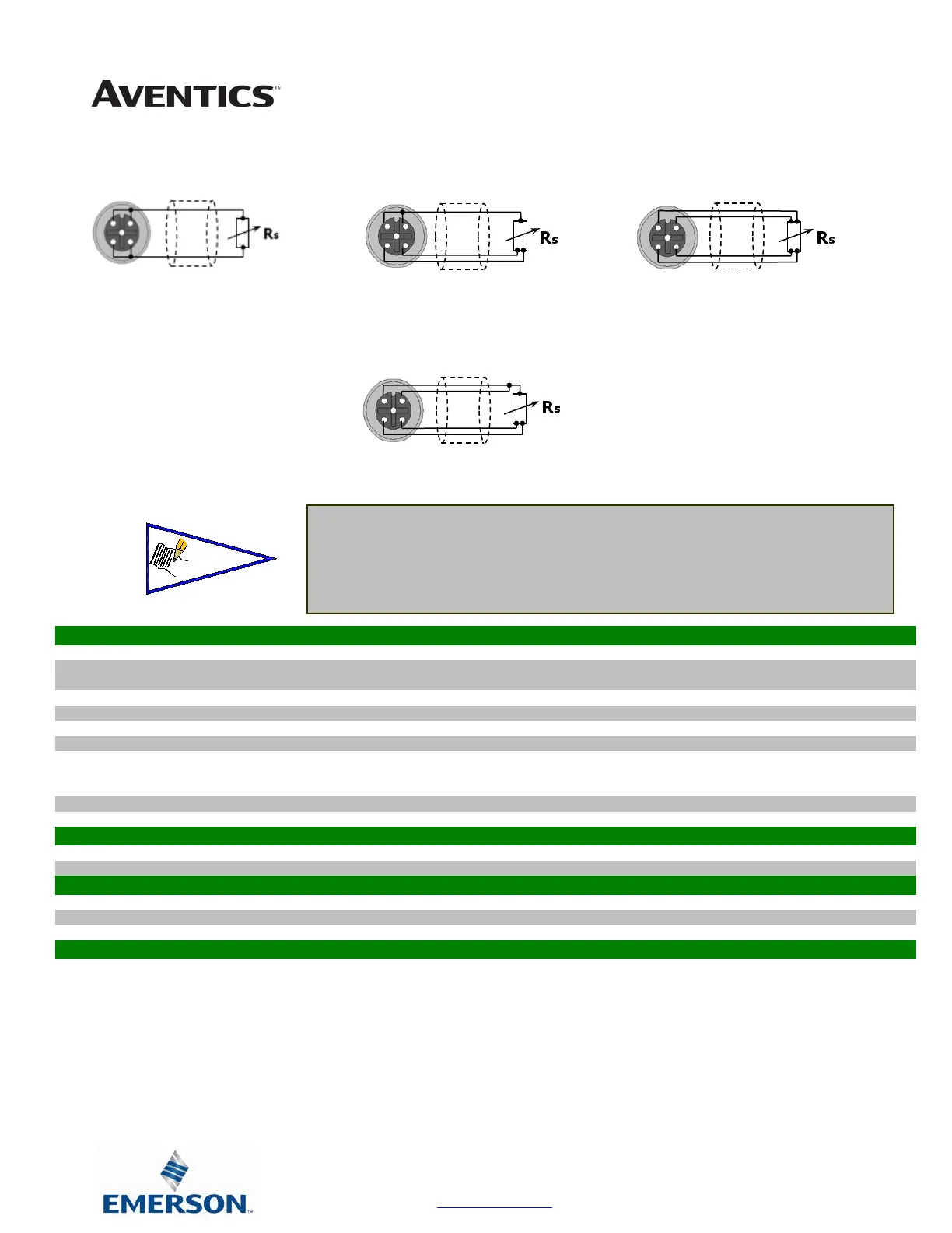
Sensor Type
Low Accuracy
Sensor Type
High Accuracy
2 Wire Cable (Fig 1)
Sensor Type
Medium Accuracy
3 Wire Cable (Fig 2)
4 Wire Cable (Fig 3)
4 Wire Sensor Type
4 Wire Cable (Fig 4)
• For maximum accuracy on a 3 wire sensor type make
identified jumper connections at the sensor end (see
Figure 3). Cable resistance, resulting from cable
length, affects measuring error; therefore use cables
that are as short as possible.
 Loading...


